
User manual

Chapter 4 - Hardware Description
4-18
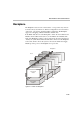
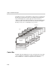
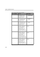
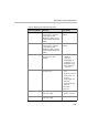
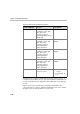
In the MGC-50, the front of the Backplane contains eight slots for Functional
Modules and an additional slot (Slot A) for the Main Control Module. The
back of the Backplane also contains eight slots for I/O cards and one
“dummy” slot. The Network Interface Module is connected via the Backplane
to I/O cards, which connect the system to the network. The Power Supply
Module provides power to the Backplane via a power bus.
Figure 4-12: MGC-50 Backplane
Control Bus
The MGC-100 and the MGC-50 use the same Control Bus. The Control Bus
connects the Main Control Module to the Functional Modules. The Control
Bus is an HDLC bus. A double bus is implemented for redundancy.
H.323 I/O
ISDN Network I/F
ATM Network I/F
MUX
Audio
Video
Data
NET I/O
ATM I/O
MUSIC I/O
Rear
B
ac
k
p
l
ane
Front
Main Control
Module
Power Supply
Module
MPI Serial Network I/F
H.323 Network I/F