Hardware Installation Guide for the Polycom SoundStructure C16, C12, C8, and SR12 1725-33169-001 Revision A
Trademark Information Polycom®, the Polycom logo design, SoundPoint® IP, SoundStation®, SoundStation VTX 1000®, ViaVideo®, ViewStation®, and Vortex® are registered trademarks of Polycom, Inc.
Contents Preparing For Installation . . . . . . . . . . . . . . . . . . . . . . . . . . . . . . . . . . 1–1 Overview . . . . . . . . . . . . . . . . . . . . . . . . . . . . . . . . . . . . . . . . . . . . . . . . . . . . . Product Features . . . . . . . . . . . . . . . . . . . . . . . . . . . . . . . . . . . . . . . . . . . . . . . . . . . . . . Installation Overview . . . . . . . . . . . . . . . . . . . . . . . . . . . . . . . . . . . . . . . . . . . . Package Contents . . . . . . . . . . . . . . . . . . .
Hardware Installation Guide for the Polycom SoundStructure Logic Interface . . . . . . . . . . . . . . . . . . . . . . . . . . . . . . . . . . . . . . . . . . . . . . . . . . . . . . . . 3–7 Audio Connections . . . . . . . . . . . . . . . . . . . . . . . . . . . . . . . . . . . . . . . . . . . . . . . . . . . . 3–8 Logic Examples . . . . . . . . . . . . . . . . . . . . . . . . . . . . . . . . . . . . . . . . . . 4–1 Logic Input . . . . . . . . . . . . . . . . . . . . . . . . . . . . . . . . . . . . . . .
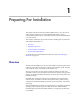
1 Preparing For Installation This chapter introduces the Polycom® SoundStructure™ C16, C12, and C8 audio conferencing devices, and the SoundStructure SR12, a sound reinforcement product which is compatible with the Polycom SoundStructure C16, C12, and C8.
Hardware Installation Guide for the Polycom SoundStructure C16, C12, C8 and SR12 Product Features The Polycom SoundStructure C16, C12, C8 and SR12 offer the following features: • 16 (C16), 12 (C12 and SR12), or 8 (C8) balanced Microphone/line-level inputs • 48 V phantom power available on all inputs • 16 (C16), 12 (C12 and SR12), or 8 (C8) balanced line-level outputs • Rear-panel Ethernet and RS-232 interfaces • Optional telephone interface cards • High-speed OBAM link to connect up to eight Sou
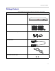
Preparing For Installation Package Contents The SoundStructure products include the components shown below. SoundStructure Device 3.
Hardware Installation Guide for the Polycom SoundStructure C16, C12, C8 and SR12 Rubber Feet 18” Conference Link2 Cable Software CD Hardware Installation Guide Warning The SoundStructure C16, C12, SR12, and C8 devices have 33, 25, 25, and 17 terminal block connectors respectively including one for the optional IR receiver accessory. For a complete list of available SoundStructure Accessories, see Accessories on page 5-1.
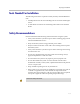
Preparing For Installation Tools Needed For Installation The following tools will be required to install your Polycom SoundStructure unit: • A Phillips head screwdriver for installing rack ears and rack-mounting the device. • A small blade screwdriver for terminating audio cables to the terminal blocks. Safety Recommendations Read and understand the following instructions before using the system: • Always disconnect the system from power before inserting plug-in cards into the SoundStructure device.
Hardware Installation Guide for the Polycom SoundStructure C16, C12, C8 and SR12 General Site Requirements Please ensure the SoundStructure side ventilation holes have at least 1 inch of clearance from the sides of the rack to allow airflow through the device. Failure to maintain clearance for airflow may increase the operating temperature of the unit beyond its maximum operating temperature of 40° C (104° F).
2 Installing The SoundStructure C16, C12, C8, And SR12 This chapter provides information on the Polycom SoundStructure product, rack-mount, and installation procedures. • Panel Diagrams • Installing The Hardware Panel Diagrams This section describes the front and rear-panels of the Polycom SoundStructure C16. Warning The graphics shown in this guide show the Polycom SoundStructure C16 audio conferencing device. The SoundStructure C12, C8, and SR12 are all very similar in appearance to the C16.
Hardware Installation Guide for the Polycom SoundStructure C16, C12, C8, And SR12 Front-Panel The front-panel of the Polycom SoundStructure C16 is shown below with the front panel door open, revealing the serial number label and the System Status LED. TM SoundStructure C16 Serial number on Front panel door System Status LED Front-Panel LED Interpretation The front-panel LEDs are interpreted as follows: 2-2 LED Color State Description Status Green Flashing The system is starting up.
Installing The SoundStructure C16, C12, C8, And SR12 Rear Panel The rear-panel of the Polycom SoundStructure C16 is shown in the following figure.
Hardware Installation Guide for the Polycom SoundStructure C16, C12, C8, And SR12 • Connect AC power. (See page 2-19.) • Configure devices using SoundStructure Studio software. (See page 2-20.) Plug-in Card Installation Each SoundStructure device can have a plug-in card installed for a total of eight plug-in cards in a collection of eight SoundStructure devices.
Installing The SoundStructure C16, C12, C8, And SR12 3. Insert the plug-in card into the slotted rails and push until it is tight into the slot. PHONE LINE PIN 2: TXD PIN 3: RXD PIN 5: GROUND PIN 7: CTS PIN 8: RTS RS-232 LAN C-LINK2 IN OBAM OUT IR 12V 4. Tighten the thumbscrews on the rear-panel of the plug-in card. 5. If no further installation steps are required, plug in the AC power cable; otherwise, continue with the remainder of the installation steps prior to applying power.
Hardware Installation Guide for the Polycom SoundStructure C16, C12, C8, And SR12 Rack-Mounting The Polycom SoundStructure Device The Polycom SoundStructure can be mounted in an equipment rack, or placed on a tabletop or other flat surface, or mounted under the table with the optional undertable mounting kit. Each SoundStructure device requires one rack space and does not require additional empty rack spaces above or below the device.
Installing The SoundStructure C16, C12, C8, And SR12 Connecting To The LAN Interface The SoundStructure device's Ethernet interface (as shown following figure) is a 10/100 Mbps interface that supports Auto-MDIX (medium dependent interface crossover). Auto-MDIX enables the use of a standard CAT5e cable to connect directly from the SoundStructure device to either an Ethernet network or to a computer. The SoundStructure device will detect the connection and work appropriately.
Hardware Installation Guide for the Polycom SoundStructure C16, C12, C8, And SR12 have an RJ45 plug form-factor (with a different pinout from standard Ethernet cables - see Conference Link2 for pinout details) to enable field termination of custom length cables using standard RJ45 plugs and standard crimping tools.
Installing The SoundStructure C16, C12, C8, And SR12 Warning Do not use Conference Link2 to connect multiple SoundStructure devices together. The OBAM link must be used for connecting multiple SoundStructure devices. Using Multiple SoundStructure Devices With OBAM Link Interface Each SoundStructure device has OBAM IN and OUT connectors (as shown in the following figure) that may be used to link up to eight SoundStructure devices1.
Hardware Installation Guide for the Polycom SoundStructure C16, C12, C8, And SR12 Because the OBAM interface is bi-directional, data will flow in both directions on the single cable between devices. Due to this bi-directionality, do not loop the OBAM link connections (as follows).
Installing The SoundStructure C16, C12, C8, And SR12 the device with no OBAM OUT connection. The device ID is important for ensuring that a system is cabled properly so that it matches the configuration that will be uploaded to the system. As an example, consider the following figure that shows a SoundStructure C12 linked with a C8.
Hardware Installation Guide for the Polycom SoundStructure C16, C12, C8, And SR12 4: Amplifier 2 (Right) Plugin Card: Single Line Telephone 1: Phone In, Phone Out C-Link2 Interface: Polycom HDX C8 (bus id: 2) C-Series Mic Input 1: Table Mic 13 2: Table Mic 14 3: Table Mic 15 4: Table Mic 16 5: Lectern Mic 6: Wireless Mic 7: Program Audio (Left) 8: Program Audio (Right) Wiring the system as described in the wiring report and linking multiple devices as indicated to ensure the device ID’s of the system mat
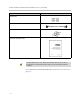
Installing The SoundStructure C16, C12, C8, And SR12 480-00 Series Data +12V GND 1 2 3 RS-232 The RS-232 interface is capable of running up to 115,200 bps and has a default rate of 9,600 bps, eight data bits, no parity, one stop bit (8-N-1). The pinout of the connection and the recommended straight-through cabling to a control system is shown in the following figure.
Hardware Installation Guide for the Polycom SoundStructure C16, C12, C8, And SR12 SoundStructure Control System Pin Signal Pin Signal 1 - 1 - 2 TX 2 RX 3 RX 3 TX 4 - 4 - 5 Ground 5 Ground 6 - 6 - 7 CTS 7 RTS 8 RTS 8 CTS 9 - 9 - At rates at or above 38,400 bps, it is recommended that flow control be enabled on the control system.
Installing The SoundStructure C16, C12, C8, And SR12 connections in the following figure. To connect the SoundStructure device's audio input and output to unbalanced audio equipment, follow the wiring in the unbalanced audio connections below.
Hardware Installation Guide for the Polycom SoundStructure C16, C12, C8, And SR12 Internal to the SoundStructure device is a fuse that will trigger if the current draw on Pin 1 exceeds 500 mA. The fuse will reset itself once the excessive load is removed. As there are two logic connectors, there are a total of twenty-two logic inputs, twenty-two logic outputs, two analog gain inputs, and two +5 V supplies and two logic grounds per SoundStructure device.
Installing The SoundStructure C16, C12, C8, And SR12 8 Logic Output 18 21 9 Logic Output 19 22 Logic Input 19 Logic Input 20 10 Logic Output 20 23 Logic Input 21 11 Logic Output 21 24 Logic Input 22 12 Logic Output 22 25 Ground 13 Analog Gain 2 Logic Inputs All digital logic inputs (logic inputs 1 - 22) operate as contact closures and may either be connected to ground (closed) or not connected to ground (open). The logic input circuitry is shown in the following figure.
Hardware Installation Guide for the Polycom SoundStructure C16, C12, C8, And SR12 Chapter 4 Logic Examples provides an example of how to use the analog gain input pin. SoundStructure Logic Input 5V Analog Voltage Value Logic Pin 1 (+5V) Analog Gain Input Pin Logic Pin 25 (Ground) Logic Outputs All logic outputs are configured as open-collector circuits and may be used with external voltage sources. The maximum voltage that should be used with the logic outputs is 60 V with a maximum current of 500 mA.
Installing The SoundStructure C16, C12, C8, And SR12 When the logic output is set low (off), the transistor will turn off and an open circuit will be created between the logic output and the chassis ground preventing any flow of current as shown in the following figure. Logic Output Pin Logic Output High (On) Chassis Ground Logic Output Pin Logic Output Low (Off) Chassis Ground See Logic Examples for information on how to wire the logic interface for common logic applications.
Hardware Installation Guide for the Polycom SoundStructure C16, C12, C8, And SR12 For more information, see Front-Panel LED Interpretation. Power cord plugged in Power cord not plugged in Configuring The SoundStructure Devices For information on configuring software for the SoundStructure, see the manual entitled Design Guide for the Polycom SoundStructure C16, C12, C8, and SR12.
3 Specifications Technical Specifications Dimensions • 19" (483 mm) W x 13.5" (343 mm) L x 1.75" (45 mm) H (one rack unit) Weight • 12 lbs. (5.5 kg) dry, 14 lbs. (6.4 kg) shipping Connectors • RS-232: DB9F • OBAM In/Out: IEEE 1394B • CLINK2: RJ45 • LAN: RJ45 • Control/Status: DB25F • Audio: Mini (3.5 mm) quick connect terminal blocks • IR Receive: Mini (3.
Hardware Installation Guide for the Polycom SoundStructure C16, C12, C8, and SR12 Thermal • Thermal Dissipation (Btu/hr): 266 Btu/hr (C16), 230 Btu/hr (C12), 215 Btu/hr (SR12), 200 Btu/hr (C8) • Operating temperature 0 - 40° C (104° F) Inputs • Phantom power: 48 V DC through 6.8 kOhm series resistor per leg, 7.5 mA per channel, software selectable • Analog input gain: -20 to 64 dB on all inputs in 0.5 dB steps, software adjustable • Maximum input amplitude: +20.
Specifications • THD+N: < 0.
Hardware Installation Guide for the Polycom SoundStructure C16, C12, C8, and SR12 Pin Out Summary Warning Drawings and part numbers are provided for reference only. Other than cables provided by Polycom, Polycom claims no responsibility or liability for the quality, performance, or reliability of cables based on these reference drawings. Contact a Polycom reseller to order cables that meet the appropriate manufacturing tolerances, quality, and performance parameters for particular applications.
Specifications OBAM Link The OBAM cable is a standard 1394b BETA style cable. The maximum length of this cable is 10 feet (3 m). While OBAM Link uses 1394b cables, the underlying bus protocol is not IEEE1394b compliant which means that external IEE1394b devices will not be compatible with OBAM Link. Using IEE1394b hubs or repeaters will not extend the length of OBAM and any non-SoundStructure approved device that is placed on the OBAM Link will prevent OBAM Link from operating properly.
Hardware Installation Guide for the Polycom SoundStructure C16, C12, C8, and SR12 IR Receiver The IR receiver port on the rear-panel of a SoundStructure device is shown in the following figure. PIN 2: TXD PIN 3: RXD PIN 5: GRO PIN 7: CTS PIN 8: RTS OUT IR 12V The IR receiver port accepts a standard 3.5 mm terminal block which should be terminated to the IR receiver as shown in the following figures.
Specifications SoundStructure Control System Pin Signal Pin Signal 1 - 1 - 2 TX 2 RX 3 RX 3 TX 4 - 4 - 5 Ground 5 Ground 6 - 6 - 7 CTS 7 RTS 8 RTS 8 CTS 9 - 9 - Logic Interface Pin 13 Pin 1 Pin 25 Pin 13 Pin 14 REMOTE CONTROL 1 Pin 25 Pin 1 Pin 14 REMOTE CONTROL 2 Remote Control 1 Pin Signal Pin Signal 1 +5 V 14 Logic Input 1 2 Logic Output 1 15 Logic Input 2 3 Logic Output 2 16 Logic Input 3 4 Logic Output 3 17 Logic Input 4 5 Logic
Hardware Installation Guide for the Polycom SoundStructure C16, C12, C8, and SR12 11 Logic Output 10 24 Logic Input 11 12 Logic Output 11 25 Ground 13 Analog Gain 1 Remote Control 2 Pin Signal Pin Signal 1 +5 V 14 Logic Input 12 2 Logic Output 12 15 Logic Input 13 3 Logic Output 13 16 Logic Input 14 4 Logic Output 14 17 Logic Input 15 5 Logic Output 15 18 Logic Input 16 6 Logic Output 16 19 Logic Input 17 7 Logic Output 17 20 Logic Input 18 8 Logic Output 18 21
Specifications SoundStructure device's audio input and output to other balanced or unbalanced audio equipment, follow the wiring convention in the unbalanced audio connections following figure.
Hardware Installation Guide for the Polycom SoundStructure C16, C12, C8, and SR12 3 - 10
4 Logic Examples Logic Input Contact Closure Pin 14 : Logic Input 1 Pin 25 : Ground Remote Control When the contact is closed, the logic input pin (Pin 14 in this example) is driven low (off). When the switch is open, the logic input pin will float high (on). Typical applications may be push to mute or push to talk buttons or room combining for changing the device settings based on the room configuration.
Hardware Installation Guide for the Polycom SoundStructure C16, C12, C8, and SR12 Logic Output SoundStructure Powered Relay 5 V Relay Pin 1 : +5 V External Device to be Controlled Pin 2 : Logic Output 1 Remote Control Relays rated for +5 V or lower may be driven directly from the +5 V logic connector pin 1 supply. Relays rated for more than +5 V will need an external power supply as described in the next example.
Logic Examples • The current from the power supply and relay circuit does not exceed 500 mA. As with the 5 V relay example, when the logic output pin (Pin 2 in this example) is set on (high), the relay energizes and the relay contact is closed. When the logic output in is set off (low), current stops flowing, and the relay de-energizes and the relay contact is opened. A diode is recommended to be placed in parallel with the relay to provide a path for the discharge of the magnetic coil of the relay.
Hardware Installation Guide for the Polycom SoundStructure C16, C12, C8, and SR12 Logic Input And Output Push To Talk Microphones Remote Control Pin 14 : Logic Input 1 Pin 2 : Logic Output 1 Pin 25 : Ground Analog Input White Orange Green Shield Black Red The SoundStructure devices may be used with push to talk microphones such as the Shure MX392. When the orange (LED in) wire is connected to ground due to the SoundStructure logic output being turned on, the LED on the microphone will turn on.
Logic Examples Analog Gain Control Pin 13 : Analog Input Pin 1 : +5V 10K ohm Remote Control Pin 25 : Ground Pin 13 on each Remote control connector may be used with an analog potentiometer to provide an analog input signal that can be used to control volume or other settings within SoundStructure devices.
Hardware Installation Guide for the Polycom SoundStructure C16, C12, C8, and SR12 4-6
5 Accessories The SoundStructure product family includes the following accessories, which can be purchased separately.
Hardware Installation Guide for the Polycom SoundStructure C16, C12, C8 and SR12 5-2
6 Regulatory Notices And Warranty Information Regulatory Notices USA And Canada Pt 15 Rules This device complies with part 15 of the FCC Rules. Operation is subject to the following two conditions: This device may not cause harmful interference, and this device must accept any interference received, including interference that may cause undesired operation.
Hardware Installation Guide for the Polycom SoundStructure C16, C12, C8, and SR12 Exhibit J - Customer Information This equipment complies with Part 68 of the FCC rules and the requirements adopted by the ACTA. On the exterior of the cabinet of this equipment is a label that contains, among other information, a product identifier in the format 2HWTE01BSSTRUCTURE. If requested, this number must be provided to the telephone company.
Regulatory Notices And Warranty Information Data Equipment The table below shows which jacks are associated with which modes of operation: Mode of Operation USOC Jack Permissive RJ11C Automatic Dialing WHEN PROGRAMMING EMERGENCY NUMBERS AND/OR MAKING TEST CALLS TO EMERGENCY NUMBERS; • Remain on the line and briefly explain to the dispatcher the reason for the call. • Perform such activities in the off-peak hours, such as early morning or late evening.
Hardware Installation Guide for the Polycom SoundStructure C16, C12, C8, and SR12 EEA (European Economic Area) Including Switzerland CE Mark R & TTE Directive This SoundStructure has been marked with the CE mark. This mark indicates compliance with EEC Directives 89/336/EEC, 73/23/EEC 1999/5/EC. A full copy of the Declaration of Conformity can be obtained from Polycom Ltd, 270 Bath Road, Slough, Berkshire, SL1 4DX, UK.
Regulatory Notices And Warranty Information Ελληνική [Greek]: ΜΕ ΤΗΝ ΠΑΡΟΥΣΑ Polycom (UK) Ltd ΔΗΛΩΝΕΙ ΟΤΙ SoundStructure ΣΥΜΜΟΡΦΩΝΕΤΑΙ ΠΡΟΣ ΤΙΣ ΟΥΣΙΩΔΕΙΣ ΑΠΑΙΤΗΣΕΙΣ ΚΑΙ ΤΙΣ ΛΟΙΠΕΣ ΣΧΕΤΙΚΕΣ ΔΙΑΤΑΞΕΙΣ ΤΗΣ ΟΔΗΓΙΑΣ 1999/5/ΕΚ. Français [French]: Par la présente Polycom (UK) Ltd déclare que l'appareil SoundStructure est conforme aux exigences essentielles et aux autres dispositions pertinentes de la directive 1999/5/CE.
Hardware Installation Guide for the Polycom SoundStructure C16, C12, C8, and SR12 Magyar [Hungarian]: Alulírott, Polycom (UK) Ltd nyilatkozom, hogy a SoundStructure megfelel a vonatkozó alapvetõ követelményeknek és az 1999/5/EC irányelv egyéb elõírásainak. Norsk [Norwegian]: Polycom (UK) Ltd erklærer herved at utstyret SoundStructure er i samsvar med de grunnleggende krav og øvrige relevante krav i direktiv 1999/5/EF.
Regulatory Notices And Warranty Information Dyrektywy 1999/5/WE. Português [Portuguese]: Polycom (UK) Ltd declara que este SoundStructure está conforme com os requisitos essenciais e outras disposições da Directiva 1999/5/CE. Slovensko [Slovenian]: Polycom (UK) Ltd izjavlja, da je ta SoundStructure v skladu z bistvenimi zahtevami in ostalimi relevantnimi določili direktive 1999/5/ES.
Hardware Installation Guide for the Polycom SoundStructure C16, C12, C8, and SR12 EU Czech republic Australia Mains powered POT’s Voice Telephony without Emergency 000 dialing Warning This equipment will be inoperable when mains power fails Reference: AS/ACIF S002:2001 (incorporating Amdt 1) DECEMBER 2001 Clause 5.1.8.
Regulatory Notices And Warranty Information Korea Class A Rest Of World EMC. CLASS A ITE WARNING This is a Class A product. In a domestic environment this product may cause radio interference in which case the user may be required to take adequate measures.
Hardware Installation Guide for the Polycom SoundStructure C16, C12, C8, and SR12 Warranty Information LIMITED WARRANTY Polycom warrants to the end user ("Customer") that the product will be free from defects in workmanship and materials, under normal use and service, for one year, or such longer period as Polycom may announce publicly from time to time for particular products, from the date of purchase from Polycom or its authorized reseller.
Regulatory Notices And Warranty Information AND REMEDIES ARE EXCLUSIVE AND ARE IN LIEU OF ALL OTHER WARRANTIES, TERMS, OR CONDITIONS, EXPRESS OR IMPLIED, EITHER IN FACT OR BY OPERATION OF LAW, STATUTORY OR OTHERWISE, INCLUDING WARRANTIES, TERMS, OR CONDITIONS OF MERCHANTABILITY, FITNESS FOR A PARTICULAR PURPOSE, SATISFACTORY QUALITY, CORRESPONDENCE WITH DESCRIPTION, AND NON-INFRINGEMENT, ALL OF WHICH ARE EXPRESSLY DISCLAIMED.
Hardware Installation Guide for the Polycom SoundStructure C16, C12, C8, and SR12 6 - 12