
User's Manual


Logic Examples
4 - 3
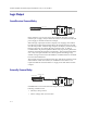
• The current from the power supply and relay circuit does not exceed 500
mA.
As with the 5 V relay example, when the logic output pin (Pin 2 in this
example) is set on (high), the relay energizes and the relay contact is closed.
When the logic output in is set off (low), current stops flowing, and the relay
de-energizes and the relay contact is opened.
A diode is recommended to be placed in parallel with the relay to provide a
path for the discharge of the magnetic coil of the relay. This current will
discharge over a very short period of time and a diode capable of handling a
large amount of surge current such as the IN4001 is recommended and is
available from several manufacturers. The IN4001 is rated up to 50 V, if higher
voltages are required, the IN4002 is rated to 100 V.
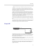
This circuit uses an Omron G7L 12 V relay with a coil resistance of 75 ohms.
For this reason, an additional series resistor between the power supply and
relay is not needed to ensure the current from the 5 V supply is less than 500
mA.
The ground connection of the power supply must be connected to the ground
pin of the logic connector (Pin 25) in order for the return currents from the
external power supply to be able to return to their source.
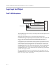
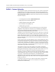
Driving An LED
SoundStructure logic outputs can be used to turn on or off LEDs. In this
example when the logic output is driven high (on), current will flow, and the
LED will turn on. When the logic output is set low (off), current will stop
flowing, and the LED will turn off.
Most standard LEDs need about 2.0 V to illuminate. In this example a 274 ohm
resistor is used to limit the current from Pin 1.
A series resistor must be used to limit the voltage and current to a safe level for
the LED.
Increasing the series resistor value will decrease the current through the circuit
and will also decrease the voltage at the input to the LED, reducing the
brightness of the LED.
LED
Remote Control
Pin 1 : +5V
Pin 2 : Logic Output 1
274 ohm