Polycom RMX 2000 Hardware Guide Version 2.0.
Copyright © 2008 Polycom, Inc. All Rights Reserved Catalog No. DOC2184B Version 2.0.2 Proprietary and Confidential The information contained herein is the sole intellectual property of Polycom, Inc. No distribution, reproduction or unauthorized use of these materials is permitted without the expressed written consent of Polycom, Inc. Information contained herein is subject to change without notice and does not represent commitment of any type on the part of Polycom, Inc.
Regulatory Notices United States Federal Communication Commission (FCC) CE Mark R&TTE Directive Part 15: Class A Statement. This equipment has been tested and found to comply with the limits for a Class A digital device, pursuant to Part 15 of the FCC Rules. Test limits are designed to provide reasonable protection against harmful interference when the equipment is operated in a commercial environment.
Regulatory Notices Chinese Communication Certificate Singapore Certificate RMX 2000 complies with IDA standards G0916-07
Polycom RMX 2000 Hardware Guide Table of Contents Hardware Description . . . . . . . . . . . . . . . . . . . . . . . . . . 1-1 Main Features .......................................................................................... 1-1 RMX 2000 Specifications ....................................................................... 1-2 Site Requirements ................................................................................... 1-3 Safety Requirements .................................................
Table of Contents ii
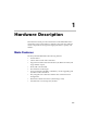
1 Hardware Description This Hardware Guide provides information on the RMX 2000 and its components. This system utilizes a modular “universal slot” platform, whose components are designed for high performance, capacity and reliance. Main Features The Polycom RMX 2000 offers the following features: • Linux® based • Chassis based on the ATCA standard • Support for standard network interfaces (IP, ISDN and LAN) and large number of ports • H.
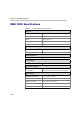
Chapter 1- Hardware Description RMX 2000 Specifications Table 1-1 Polycom RMX 2000 Specifications Physical Height 3U (13.28 cm.) Width 19” (48.26 cm.) Depth 15.74” (40 cm.) Weight Up to 16.5 Kg. Free space above MCU 3” standard installation. IP Protocols Audio G.711, G.722, G.722.1, G.729A, G.723.1, Siren14. Video H.263, H.264. Network Interfaces IP, ISDN, PSTN and LAN H.323, PSTN, LAN and SIP. Power Supply AC Input 100-240 VAC, 4-2 AMP, 50/60 Hz.
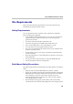
Polycom RMX 2000 Hardware Guide Site Requirements This section describes the requirements your site must meet for safe installation and operation of the system. Safety Requirements For your protection, please read these safety instructions completely before operating the equipment. • Look carefully for potential hazards in your work area: moist floors, ungrounded power cables, frayed power cords, missing safety grounds and so forth. • Locate the main circuit breaker within the room.
Chapter 1- Hardware Description • In a single rack installation, stabilizers should be attached to the rack. • In multiple rack installations, the racks should be coupled together. • Always make sure the rack is stable before extending a component from the rack. • You should extend only one component at a time - extending two or more simultaneously may cause the rack to become unstable. • Before you install the rails, determine the placement of each component in the rack.
Polycom RMX 2000 Hardware Guide RMX 2000 Components On the RMX 2000 modules are located on both the front and rear of the MCU as listed in Table 1-2, "Polycom RMX 2000 Component Description". For more information see the descriptions of the "RMX 2000 Front Panel” on page 1-5 and "RMX 2000 Rear Panel” on page 1-7. RMX 2000 Front Panel Figure 1-1 shows the front panel of the RMX 2000. The front panel provides access to the RMX 2000 main CNTL modules, MPM modules, Power Supply drawer, Status LEDs, and Fans.
Chapter 1- Hardware Description Table 1-2 Polycom RMX 2000 Component Description Component Description CPU (CNTL) Module The CPU Module controls and manages the RMX 2000. The CPU Module has an ComExpress Pentium-M 1.4 GHz processor, a 40GB hard disk drive, 1GB Compact Flash and 512MB of DDR RAM. The Operating System is Linux. Power Supply Drawer The Power Supply Module is housed in a drawer and located below the MPM Modules.
Polycom RMX 2000 Hardware Guide RMX 2000 Rear Panel The RMX 2000 rear panel contains the RTM IP board and optionally, the RTM ISDN board. In addition, the rear panel houses the main power switch, AC inlet, a circuit breaker, and additional communications ports. RTM IP The RTM IP board provides system shelf management based on the ATCA standard and connects to the backplane. It controls and monitors fans on the system and regulates power supply.
Chapter 1- Hardware Description The following items appear on the RMX 2000 rear panel: Table 1-3 1-8 RMX 2000 Rear Panel - RTM IP Component Description Item Description LAN 1 NA - Disconnected. Note: LAN 1 is covered with a plastic cap that should not be removed. LAN 2 Used for the Network connection. LAN 3 For Remote Access only using the Permanent Management Network. For more information, see the RMX 2000 Administrator’s Guide, Appendix F: "Alternate Management Network” on page G-1.
Polycom RMX 2000 Hardware Guide RTM ISDN The RTM ISDN card connects directly to an MPM card. The RTM ISDN card routes data between the MPM cards and components of the system, converts ISDN T1/E1 media to IP packets and provides connectivity to external ISDN networks. The RTM ISDN card is installed on the rear panel of the RMX interfaces between the RMX unit and the ISDN/PSTN switch. Up to two RTM ISDN cards can be installed in one RMX 2000.
Chapter 1- Hardware Description ISDN/PSTN Clock Source Each RTM ISDN card has its own primary and secondary clock source. The first span to synchronize becomes the primary clock source and the second span to synchronize becomes the secondary clock source. This clock is used to synchronize ISDN spans only (it is not the system clock). A single clock source triggers an alarm that can be turned off by setting the appropriate flag in the system configuration.
Polycom RMX 2000 Hardware Guide Cables Connected to the RTM IP & ISDN Boards All external connectors are located on the rear panel. LAN 2 Connection E1/T1 Connection Off/On switch Power Cable Figure 1-4 RMX 2000 Rear Panel View with Cables Do not remove the protective caps from LAN1, LAN3 and ShMG ports.
Chapter 1- Hardware Description RMX 2000 LEDs The RMX includes LEDs located on the front panel and rear panel. In the front panel, the LEDs reflect the state of the module. The LEDs on the rear panel indicate the state of the external connections and the status of the RTM IP board. RMX 2000 Front Panel LEDs The following items appear on the RMX 2000 front panel: Table 1-4 RMX 2000 Front Panel LED’s Component LED ID LED Color Description Green OK. Red Warning - Fan failure. Green OK.
Polycom RMX 2000 Hardware Guide Table 1-4 RMX 2000 Front Panel LED’s (Continued) Component LED ID LED Color Description MPM ERR Red ON - Major error on board. RDY Green ON - The board has completed startup successfully. ACT Amber ON - At least one participant is connected to a conference. HS Blue Flashes - Shut down process initiated by lightly pulling the CPU ejector levers. This Led flashes in synchronization with the CNTL’s board’s HS Led.
Chapter 1- Hardware Description Table 1-5 RMX 2000 RTM IP LEDs (Continued) Component 10/100 ShMG LEDs SLOT (1-4) LEDs ShMG LEDs LED Name LED Color Description LNK Green Lit with active network connection, flickers with Packet activity. 100 Amber Lit when active network is 10/ 100Mb, flickers with Packet activity. LNK (1-4) Green Lit with active network connection, flickers with Packet activity. 1Gb (1-4) Amber Lit when 1Gb connection online, flickers with Packet activity.
Polycom RMX 2000 Hardware Guide RTM ISDN The following items appear on the RTM ISDN rear panel: Table 1-6 RMX 2000 RTM ISDN Rear Panel LEDs Function Name LED Name LED Color Description LAN LED (1) LNK Green Lit with active network connection, flickers with Packet activity. 1 Gb Amber Lit when 1Gb connection online, flickers with Packet activity H/S Blue OFF - Normal.
Chapter 1- Hardware Description Component Replacement The RMX 2000 is designed with ease of maintenance in mind. Most components are swappable and are accessible directly via the front panel or the rear panel.
Polycom RMX 2000 Hardware Guide Prior to removing an MPM board the captive screws must be unscrewed and the ejector levers must be used to “power down” the card. Powering down of the card by lightly pulling on the MPM card’s ejector mechanism. Once the ejector levers have been pulled a removal sequence is initiated and the process cannot be terminated. When present, the HS LED flash on the MPM and Control Unit. When the HS led is constantly lit the card is powered down, you can remove the card.
Chapter 1- Hardware Description Replacing a powered On (hot) MPM card 1 Loosen the captive screws that fasten the card to the MCU. 2 Pull the ejector levers on the sides of the card forward and slightly outward until the blue HS LED on the card and the Control Unit start to flash. Warning! Once the removal sequence is initiated the process cannot be terminated and the HS led flashes if activated.
Polycom RMX 2000 Hardware Guide 5 Carefully slide the MPM Module out through the front panel. 6 On the card to be installed, move the ejector levers to their fully open position. 7 Slide in the replacement MPM Module. 8 Push the MPM Module firmly into the Backplane, making sure it is properly seated in its slot. 9 Ensure that the metal ejector levers are fully retracted into their housings. 10 Tighten the captive screws on the front panel of the RMX that secure the MPM Module.
Chapter 1- Hardware Description Replacing the CPU (CNTL) Module The CPU module is the management system of the RMX 2000. Use the following procedure to replace a CPU (CNTL) Module: 1 Ensure that power switch to the RMX 2000 is turned OFF (O). 2 Unscrew the captive screws on the front panel of the RMX 2000 that secure the CPU (CNTL) Module. 3 Use the metal ejector levers to pull the CPU (CNTL) Module out of its slot in the Backplane.
Polycom RMX 2000 Hardware Guide Replacing the Power Supply Drawer A single supply unit powers the RMX 2000. Use the following procedure to replace a Power Supply: 1 Ensure that power switch to the RMX 2000 is turned OFF (O). 2 Unscrew the captive screws on the front panel of the RMX 2000 that secure the Power Supply. 3 Use the metal ejector levers to pull the Power Supply Module out of its slot in the Backplane. 4 Carefully slide the Power Supply Module out through the front panel.
Chapter 1- Hardware Description Replacing the Fan Drawer Three fans are mounted in the Fan Drawer, where the airflow is from right to left. Should one of these fans fail as indicated by a Fan LED, you are required to replace the fan drawer. 1 Unscrew the captive screws on the front panel of the RMX 2000 that secure the Fan Drawer. 2 Use the metal ejector levers to pull the Fan Drawer out of its slot in the Backplane. 3 Carefully slide the Fan Drawer out through the front panel.
Polycom RMX 2000 Hardware Guide Replacing a RTM ISDN card 1 Ensure that power switch to the RMX 2000 is turned OFF (O). 2 Loosen the captive screws that fasten the card to the MCU. 3 Remove the RTM ISDN board. Use the metal ejector levers to pull the RTM ISDN Module out of its slot in the Backplane. 4 Carefully slide the RTM ISDN Module out through the front panel.
Chapter 1- Hardware Description 11 Connect the RJ-45 terminated PRI cables into any of the slots labeled PRI1 - PRI12: PRI Cables Power LAN Up to 9 PRI cables can be connected to an RTM ISDN card, with each card providing connection for up to 7 E1 or 9 T1 PRI lines. When two RTM ISDN cards are installed, up to a total of 18 PRI cables can be connected.
Polycom RMX 2000 Hardware Guide Replacing the RTM IP Board The RTM IP board on the rear of the RMX 2000 provides connectivity to all the MCU modules. Use the following procedure to replace the RTM IP board: 1 Ensure that power switch to the RMX 2000 is turned OFF (O). 2 Unscrew the captive screws on the rear panel of the RMX 2000 that secure the RTM IP board. 3 Use the metal ejector levers to pull the RTM IP board out of its slot in the Backplane.
Chapter 1- Hardware Description 1-26