Polycom RMX™ 2000 System Hardware Guide Version 6.
Trademark Information Polycom®, the Polycom “Triangles” logo, and the names and marks associated with Polycom’s products are trademarks and/or service marks of Polycom, Inc., and are registered and/or common-law marks in the United States and various other countries. All other trademarks are the property of their respective owners. Patent Information The accompanying product is protected by one or more U.S. and foreign patents and/or pending patent applications held by Polycom, Inc. © 2010 Polycom, Inc.
Regulatory Notices United States Federal Communication Commission (FCC) Part 15: Class A Statement. This equipment has been tested and found to comply with the limits for a Class A digital device, pursuant to Part 15 of the FCC Rules. Test limits are designed to provide reasonable protection against harmful interference when the equipment is operated in a commercial environment.
Regulatory Notices Compliant with European Battery Directive 2006/66/EC To comply with the European Battery Directive 2006/66/EC, dispose of weak and worn out batteries in accordance with local and national regulations. Chinese Communication Certificate Singapore Certificate Taiwan Complies with IDA standards DA101619 Russian Communication Certificate The Polycom RMX™ 2000 complies with the Russian Ministry of Communication requirements stated in certificate OC/1-MM-15.
Polycom RMX 2000 Hardware Guide Table of Contents Hardware Description . . . . . . . . . . . . . . . . . . . . . . . . . . 1-1 Main Features .......................................................................................... 1-1 RMX 2000 Specifications ....................................................................... 1-2 System Capacities ................................................................................... 1-3 Site Requirements ...................................................
Table of Contents Removing the MPM/MPM+ Card from the MCU .......... 1-32 Installing the Replacement MPM/MPM+ Card .............. 1-33 Installing a New MPM/MPM+ Card in a Powered On RMX 2000 ......................................................................................................... 1-33 Replacing a RTM ISDN Card ...................................................... 1-34 Replacing the RTM IP Card ........................................................
1 Hardware Description This Hardware Guide provides information on the RMX 2000 and its components. This system utilizes a modular “universal slot” platform, whose components are designed for high performance, capacity and reliance. Main Features The Polycom RMX 2000 offers the following features: • Linux® based • Chassis based on the ATCA standard • Support for standard network interfaces (IP, ISDN and LAN) and large number of ports. • H.
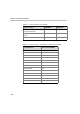
Chapter 1- Hardware Description RMX 2000 Specifications Table 1-1 Polycom RMX 2000 Specifications Physical Height 3U (13.25 cm.) Width 19” (48.26 cm.) Depth 15.74” (40 cm.) Weight Up to 16.5 Kg. IP Protocols Audio G.711, G.722, G.722.1, G.729A, G.723.1, Siren14. Video H.261, H.263, H.264. Network Interfaces IP, ISDN, PSTN and LAN H.323, SIP, PSTN, LAN and ISDN. Power Supply AC Input/ Range, BTU Voltage range: 100-240 VAC, 4-8 AMP, 50/60 Hz. Maximum BTU output: 3070 per hour.
Polycom RMX 2000 Hardware Guide System Capacities The following table summarizes the different system capacities. Table 1-2 System Functions and Capacities System Functions MPM Mode MPM+ Mode Maximum no.
Chapter 1- Hardware Description Table 1-2 System Functions MPM Mode MPM+ Mode Number of HTTP (Web) clients connected to the MCU 50 50 Maximum number Address Book entries 1000 1000 Maximum number of Users 100 100 Table 1-3 1-4 System Functions and Capacities System Resource Capacities According to Video Resolution Video Resolution Resources with MPM+ HD Support CP / VSW PSTN 400 VOIP 800 CIF 160 SD30 60 720p 40 1080p30fps 20 720p VSW 2Mb 160 1080p VSW 2Mb 160 720 VSW 4Mb
Polycom RMX 2000 Hardware Guide Site Requirements This section describes the requirements your site must meet for safe installation and operation of the system. Safety Requirements For your protection, please read these safety instructions completely before operating the equipment. • Look carefully for potential hazards in your work area: moist floors, ungrounded power cables, frayed power cords, missing safety grounds and so forth. • Locate the main circuit breaker within the room.
Chapter 1- Hardware Description • In a single rack installation, stabilizers should be attached to the rack. • In multiple rack installations, the racks should be coupled together. • Always make sure the rack is stable before extending a component from the rack. • You should extend only one component at a time - extending two or more simultaneously may cause the rack to become unstable. • Before you install the rails, determine the placement of each component in the rack.
Polycom RMX 2000 Hardware Guide RMX 2000 Components On the RMX 2000 components are located on both the front and rear of the MCU as listed in Table 1-4, "Polycom RMX 2000 Component Description". For more information see the descriptions of the "RMX 2000 Front Panel” on page 1-7 and "RMX 2000 Rear Panel” on page 1-10. Please verify the type of chassis used on your RMX 2000. Starting with version 4.0, a new environmentally friendly RMX 2000 chassis is in use.
Chapter 1- Hardware Description Table 1-4 Polycom RMX 2000 Component Description Component Description CNTL (CPU) Module The CNTL module controls and manages the RMX 2000. The CNTL module has an ComExpress Pentium-M 1.4GHz processor, a 40GB hard disk drive, 1GB Compact Flash and 1GB of DDR RAM. The Operating System is Linux. Power Supply Drawer The Power Supply drawer is located below the MPM/ MPM+ Cards and is connected to the backplane by means of a power connector.
Polycom RMX 2000 Hardware Guide Table 1-4 Polycom RMX 2000 Component Description (Continued) Component Description Multi Processor Module+ (MPM+) Card The MPM+ cards, perform the various RTP, audio and video processing functions on the RMX 2000 unit.
Chapter 1- Hardware Description RMX 2000 Rear Panel The RMX 2000 rear panel contains the RTM IP card and optionally, the RTM ISDN card. The RTM IP card must be located on the bottom slot in the rear of the RMX 2000. In addition, the rear panel houses the main power switch, AC inlet, a circuit breaker, and additional communications ports. RTM IP The RTM IP card provides system management based on the ATCA standard and connects to the backplane.
Polycom RMX 2000 Hardware Guide The following items appear on the RMX 2000 rear panel: Table 1-5 RMX 2000 Rear Panel - RTM IP Component Description Item Description LAN 1 NA - Disconnected. Note: LAN 1 is covered with a plastic cap that should not be removed. LAN 2 Used for the Network connection. LAN 3 For Remote Access only using the Alternate Management Network. For more information, see the RMX 2000 Administrator’s Guide, Appendix F: "Alternate Management Network” on page G-1.
Chapter 1- Hardware Description RTM ISDN The RTM ISDN card connects directly to an MPM/MPM+. The RTM ISDN card routes data between the MPM/MPM+ cards and components of the system, converts ISDN T1/E1 media to IP packets and provides connectivity to external ISDN networks. The RTM ISDN card is installed on the rear panel of the RMX interfaces between the RMX unit and the ISDN/PSTN switch. Up to two RTM ISDN cards can be installed in one RMX 2000.
Polycom RMX 2000 Hardware Guide ISDN/PSTN Clock Source Each RTM ISDN card has its own primary and secondary clock source. The first span to synchronize becomes the primary clock source and the second span to synchronize becomes the secondary clock source. This clock is used to synchronize ISDN spans only (it is not the system clock). A single clock source triggers an alarm that can be turned off by setting the appropriate flag in the system configuration.
Chapter 1- Hardware Description RMX 2000 LEDs The RMX includes LEDs located on the front panel and rear panel. In the front panel, the LEDs reflect the state of the components. The LEDs on the rear panel indicate the state of the external connections and the status of the RTM IP card. RMX 2000 Front Panel LEDs The following items appear on the RMX 2000 front panel: Table 1-6 RMX 2000 Front Panel LED’s Component Fan Status Power Status 1-14 LED ID LED Color Description Green OK.
Polycom RMX 2000 Hardware Guide Table 1-6 RMX 2000 Front Panel LED’s (Continued) Component LED ID LED Color Description MPM/MPM+ Card ERR Red ON - Major error on card. Flashes - During card startup. RDY Green ON - The card has completed startup successfully. Flashes - During card startup. ACT Amber ON - At least one participant is connected to a conference. Flashes - During card startup. HS Blue Flashes - Shut down process initiated by lightly pulling the CPU ejector levers.
Chapter 1- Hardware Description Table 1-6 RMX 2000 Front Panel LED’s (Continued) Component LED ID LED Color Description CNTL Unit ERR Red ON - Major system error. In case of an active alarm this light is ON, and the RDY green is OFF. OFF - Normal. Flashes - During system startup. RDY Green ON - CPU card has successfully completed startup. This light turns green after completing the entire system configuration. OFF - Turns OFF when the ERR red LED is activated. Flashes - During system startup.
Polycom RMX 2000 Hardware Guide RMX 2000 Rear Panel LEDs RTM IP The following LEDs appear on the RTM IP card: Table 1-7 RMX 2000 RTM IP LEDs Component LED Name LED Color Description LAN LEDs (1-3) LNK Green ON with an active network connection, flickers with Packet activity. 1 Gb Amber ON with a 1Gb online connection, flickers with Packet activity. LNK Green ON with an active network connection, flickers with Packet activity.
Chapter 1- Hardware Description Table 1-7 RMX 2000 RTM IP LEDs (Continued) Component LED Name LED Color Description ShMG LEDs ERR Red ON - Major error on RTM card. Flashes - During system startup. ACT Red ON - Packet flow to and from the MCU chassis. Flashes - During system startup. RDY Green ON - RTM IP card has successfully completed startup. Flashes - During system startup. HS Blue OFF - Normal. Flashes - During power down process. ON - RTM IP card may be removed.
Polycom RMX 2000 Hardware Guide RTM ISDN The following LEDs appear on the RTM ISDN: Table 1-8 RMX 2000 RTM ISDN LEDs Function Name LED Name LED Color Description LAN LED (1) LNK Green ON with an active network connection, flickers with Packet activity. 1 Gb Amber ON when 1Gb connection is online, flickers with Packet activity. H/S Blue OFF - Normal.
Chapter 1- Hardware Description MPM and MPM+ Configuration Modes The RMX unit can work with either MPM or MPM+ (but not with both simultaneously) media cards. The card Type installed in the system determines the Card Configuration Mode. When MPM card is installed in the MCU, it operates in MPM Mode. When MPM+ cards are installed, the RMX operates in MPM+ Mode giving the administrator enhanced control and monitoring of resource allocation and usage within the system.
Polycom RMX 2000 Hardware Guide MPM+ Resource Capacities The MPM+ card offers increased resource capacities and capabilities. Three MPM+ card assemblies are available: MPM+ 80, MPM+ 40 and MPM+ 20 offering various resource capacities for CP conferences. In CP conferences: • Frame rate has been increased – with HD720p now up to 60fps. • Video resolution has been increased up to HD1080p. • Bandwidth is up to 4 Mbps. Table 3 summarizes the increased video capacities of the various MPM+ card assemblies.
Chapter 1- Hardware Description MPM and MPM+ Modes MPM+ and MPM cards installed in the system cannot be used simultaneously. Therefore, the RMX can operate in either MPM or MPM+ Mode. Operating Mode Selection During Startup / Restart • When started with Version 4.0 installed, the RMX enters MPM+ Mode by default, even if no media cards are installed. • When upgrading a system from Version 3 (or lower) with Version 4.
Polycom RMX 2000 Hardware Guide Table 4 Card Configuration Mode After Next Restart Current Operating Mode MPM Media Cards Installed Card(s) Supported Card(s) Disabled Operating Mode After Next Restart MPM or MPM x 2 All None MPM MPM and MPM+ MPM Only MPM+ Only MPM+ MPM+ or MPM+ x 2 None All MPM+ Example 1: Current status An RMX has two MPM cards installed. The Card Configuration Mode is MPM. Both MPM cards are enabled. Action 1. Remove one MPM card. 2. Insert one MPM+ card.
Chapter 1- Hardware Description Example 2: Current status An RMX has one MPM+ card installed. The Card Configuration Mode is MPM+. and the MPM+ card is enabled. Action 1. Remove the MPM+ card. 2. Insert one MPM card. Result The Card Configuration Mode remains MPM+. The inserted MPM card is disabled.
Polycom RMX 2000 Hardware Guide RMX Chassis Types The RMX chassis can be of type A/B/C or D. The environmentally friendly D-type chassis (indicated by the letter D in the Part Number) is required for use with MPM+ card(s). The chassis type can be viewed in the Hardware Monitor, by right clicking Slot 0 and then clicking Properties. The RMX 2000 - General Information dialog box opens. The RMX Part Number contains the letter A/B/C/D that represents the chassis type, as shown in the capture above.
Chapter 1- Hardware Description Component Replacement The RMX 2000 is designed with ease of maintenance in mind. Most components are swappable and are accessible directly via the front panel or the rear panel. Only MPM/MPM+ cards are Hot Swappable. The RTM IP and RTM ISDN card are not Hot Swappable. System shutdown is required when replacing the RTM ISDN or RTM IP card. The following components can be replaced when they are faulty: • CNTL Module, see "Replacing the CNTL Module” on page 1-28.
Polycom RMX 2000 Hardware Guide Types of Ejector Levers on RMX Components On the RMX, 2 types of ejector levers can be attached to the cards: • An all metal (silver) lever • A modified PMC compatible ejector lever covered by plastic caps with a lock catch Using the All Metal Ejector Lever This ejector lever can be moved to 3 positions: • Closed - The ejector levers are fully retracted and pushed up against the card’s panel • Partially Open - For card powering down mode.
Chapter 1- Hardware Description Closing the Lever - Make sure that the lever is in an open position and push card close to the chassis till the lever engages. With your index finger holding the “handle” and your thumb holding the catch fully to left, push the card against the chassis whilst closing the lever. Use your thumb to push the card into place by pushing your thumb to the right and locking the catch into a locked position. Make sure that the lever is locked.
Polycom RMX 2000 Hardware Guide 3 Use the metal ejector levers to pull the CNTL Module out of its slot in the Backplane. 4 Carefully slide the CNTL Module out through the front panel. 5 On the CNTL Module to be installed, move the ejector lever to the fully open position. 6 Slide in the replacement CNTL Module. 7 Push the CNTL Module firmly into the Backplane, making sure it is properly seated in its slot. 8 Ensure that the metal ejector levers are fully retracted into their housings.
Chapter 1- Hardware Description Replacing the Power Supply Module A single supply unit powers the RMX 2000. Use the following procedure to replace a Power Supply: Please verify the type of power supply used on your RMX 2000. Do not insert a different type of power supply than the current type installed on your system. 1 Ensure that the power switch on the RMX 2000 is turned OFF (O) and that the power cords are disconnected from the MCU.
Polycom RMX 2000 Hardware Guide Replacing the Fan Drawer Three fans are mounted in the Fan drawer, where the airflow is from right to left. Should one of these fans fail as indicated by a Fan LED, you are required to replace the Fan drawer. 1 Unscrew the captive screws on the front panel of the RMX 2000 that secure the Fan drawer. 2 Use the metal ejector levers to pull the Fan drawer out of its slot in the Backplane. 3 Carefully slide the Fan drawer out through the front panel.
Chapter 1- Hardware Description Replacing a Faulty MPM/MPM+ Card Removing the MPM/MPM+ Card from the MCU All MPM/MPM+ cards can be installed or removed while the RMX 2000 is powered on and operating. Prior to removing an MPM/MPM+ card the captive screws must be unscrewed and the ejector levers must be opened to initiate a “power down” on the card. 1 If applicable, loosen the captive screws and remove the slot cover.
Polycom RMX 2000 Hardware Guide 5 Carefully slide the MPM/MPM+ card out through the front panel. Installing the Replacement MPM/MPM+ Card 1 On the card to be installed, move the ejector levers to their fully open position. 2 Slide in the replacement MPM/MPM+ card. 3 Push the MPM/MPM+ card firmly into the Backplane, making sure it is properly seated in its slot. 4 Ensure that the metal ejector levers are fully retracted into their housings.
Chapter 1- Hardware Description The blue HS LEDs on the MPM/MPM+ card and the Control Unit start flashing and the power on cycle for the card is initiated: — The card’s resources are added to the system resources list — The number of available ports on the RMX is increased to the current CFS license level — Port usage is re-calculated and the Port Gauges and Video/Voice Port Configuration are updated When the power on cycle of the MPM/MPM+ card is completed, the blue HS LEDs will turn OFF.
Polycom RMX 2000 Hardware Guide 6 Slide in the replacement RTM ISDN card. 7 Insert the card into the slot until the ejector levers touch the front edge of the card cage. 8 Push the ejector levers to their fully closed position. 9 Tighten the captive screws on each side of the rear panel of the card, securing the RTM ISDN card to RMX. 10 Turn ON the RMX 2000.
Chapter 1- Hardware Description Replacing the RTM IP Card The RTM IP card on the rear of the RMX 2000 provides connectivity to all the MCU modules. Use the following procedure to replace the RTM IP card: 1 Ensure that the power switch on the RMX 2000 is turned OFF (O). 2 Unscrew the captive screws on the rear panel of the RMX 2000 that secure the RTM IP card. 3 Use the metal ejector levers to pull the RTM IP card out of its slot in the backplane.