Using the Shure® MX392 Push to Talk Microphone with Vortex® Devices Application Note Polycom Installed Voice Business Group September 2004 Rev.
Table of Contents TABLE OF CONTENTS......................................................................................................................... 2 SHURE MX392 BASICS....................................................................................................................... 3 Logic Port.......................................................................................................................................................................
SHURE® MX392 BASICS The Shure MX392 is a surface-mount, electret microphone that includes a programmable membrane on/off switch that can be controlled externally via logic input / output terminals. This application note explores how to connect the MX392 to a Vortex device (EF2280, EF2241, EF2201, EF2210, or EF2211) as well as how to program the Vortex device and MX392 to achieve the desired control over the membrane switch.
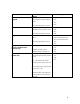
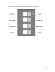
Switch Behavior User Action Required / LED Behavior Push to Mute, Release to Talk (As Press and hold switch to temporarily mute microphone; release switch to Shipped) unmute. Push to Talk, Release to Mute Toggle: Push On/Push Off Microphone Always Active (switch available for logic functions only) Automatic Mixer Mode (MX392 Models only) DIP Switch Settings S1 = OFF S2 = OFF S3 = OFF S4 = OFF LED on when microphone is active.
Here is a drawing showing the functionality that is assigned to each DIP Switch: 5
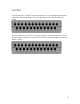
LOGIC PORT The Logic Input port is a female DB-25 connector where pins 1-24 can be programmed to execute commands via the Logic Input page. Pin 25 is the ground pin and it can sink up to 500 mA of current. The Logic Output port is a female DB-25 connector where pins 1-20 can be programmed. Pins 2125 are ground pins. Each pin can source up to 20 mA of current and each ground pin can sink up to 100 mA of current.
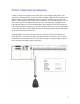
PHYSICAL CONNECTIONS AND GROUNDING In order to connect the microphone to the Vortex Device, first connect the audio portion of the microphone to the Vortex Device: Connect the Positive conductor (Red) to the Positive terminal, the Negative conductor (Black) to the Negative terminal, and the Ground wire (gray) to the Ground terminal.
TOGGLE OPERATION (PUSH TO TALK) Let's say that you want MX392 to be muted by default. If someone pushes the membrane switch, you want the microphone to stay unmuted until the user presses the switch to mute the microphone. You also want the LED to illuminate when the microphone is unmuted. First, set DIP Switch S1, S2, and S3 to ON and set S4 to OFF. Then, connect SWTICH OUT to one of the Logic Input pins 1-24. Connect LOGIC GND to Logic Output pins 21-25.
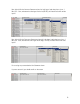
Now, right click in the ACTIVATED COMMAND column for Logic Input 1 and select INSERT, INPUT, 1, MUTE, OFF. Now, whenever the switch goes Active Low (0V DC), the Vortex Device will unmute Input 1. Now, right click in the DEACTIVATED COMMAND column for Logic Input 1 and select INSERT, INPUT, 1, MUTE, ON. Now, whenever the switch goes Active High (+ 5V DC), the Vortex Device will mute Input 1. Do not assign any command to the HELD COMMAND column.
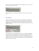
Make sure that the physical wiring works by pressing the membrane switch. You should see the LED above the pin assignment lit in green: Repeat the above process for each MX392 microphone that you want to connect to the Vortex Device. LOGIC OUTPUT Go to the Logic Output page of Conference Composer. If the LED IN wire is connected to Logic Output pin 1, then you need to assign Pin 1 by left-clicking the desired pin in the DB-25 graphic. The pin will turn color from gray to pink.
Next, right click in the ACTIVATED COMMAND column for Logic Input 1 and select INSERT, INPUT, 1, MUTE, OFF. Now, whenever the microphone is unmuted (Mute = False), the LED will illuminate on the MX392. Next, right click in the DEACTIVATED COMMAND column for Logic Input 1 and select INSERT, INPUT, 1, MUTE, ON. Now, whenever the microphone is muted (Mute = True), the LED will not illuminate on the MX392.
Make sure the LED works as designed. If you press the membrane switch, you should see the LED above the pin illuminate in Conference Composer as well as on the MX392. Since the switch is a toggle switch, the LED will stay lit until the switch is pushed again: When the membrane switch is pushed again, the Vortex Device toggles the state from unmuted to muted. Now, the LED should not be illuminated since the input from the MX392 is now muted.
TOGGLE OPERATION (PUSH TO MUTE) Let's say that you want MX392 to be unmuted by default. If someone pushes the membrane switch, you want the microphone to stay muted until the user presses the switch to unmute the microphone. You also want the LED to illuminate when the microphone is unmuted and not illuminate when the microphone is muted. First, set DIP Switch S1, S2, and S3 to ON and set S4 to OFF. Then, connect SWTICH OUT to one of the Logic Input pins 1-24. Connect LOGIC GND to Logic Output pins 21-25.
Now, right click in the ACTIVATED COMMAND column for Logic Input 1 and select INSERT, INPUT, 1, MUTE, ON. Now, whenever the switch goes Active Low (0V DC), the Vortex Device will mute Input 1. Now, right click in the DEACTIVATED COMMAND column for Logic Input 1 and select INSERT, INPUT, 1, MUTE, OFF. Now, whenever the switch goes Active High (+ 5V DC), the Vortex Device will unmute Input 1. Do not assign any command to the HELD COMMAND column.
Repeat the above process for each MX392 microphone that you want to connect to the Vortex Device. LOGIC OUTPUT Go to the Logic Output page of Conference Composer. If the LED IN wire is connected to Logic Output pin 1, then you need to assign Pin 1 by left-clicking the desired pin in the DB-25 graphic. The pin will turn color from gray to pink. Next, right-click on the pin and reverse the polarity.
Next, right click in the DEACTIVATED COMMAND column for Logic Input 1 and select INSERT, INPUT, 1, MUTE, ON. Now, whenever the microphone is muted (Mute = True), the LED will not illuminate on the MX392. Here is what the screen should look like when you are finished: Make sure the LED works as designed. If you press the membrane switch, you should see the LED above the pin illuminate in Conference Composer as well as on the MX392.
When the membrane switch is pushed again, the EF Device toggles the state from unmuted to muted. Now, the LED should not be illuminated since the input from the MX392 is now muted. Both LED's (Conference Composer and MX392) should not be illuminated: TOGGLE OPERATION MUTE ALL EXAMPLE Let's say that you have 2 Vortex units linked together via EFBus--1 EF2280 at Device ID 00 and 1 EF2241 at Device ID 01.
MACROS Go to the MACROS page of Conference Composer. To make things easy, label Macro 0 as MUTE ON and label Macro 1 as MUTE OFF. Then, for each microphone that is physically connected to the Vortex, add commands to Macro 0 that mute the microphones and add commands to Macro 1 that unmute the microphones.
In order for one microphone to mute all microphones, we need to be able to mute and unmute the microphones on all units regardless of whether a microphone is muted from the Vortex EF2280 or the EF2241. To accomplish this, we will use the BROADA command to send MUTEI commands from one unit to the other unit. The BROADA command broadcasts any command that is after the colon.
Repeat that same process for Inputs 2-4 of the Vortex EF2241. The, perform the same procedure to unmute Inputs 1-4 on the Vortex EF2241. Remember that there is a colon after the BROADA command.
Follow the same procedure for muting the Inputs 1-8 on the Vortex EF2280 from the EF2241. Here is what the Macros page for the Vortex EF2241 should look like when you are finished: LOGIC INPUT Go to the Logic Input page of Conference Composer. If the SWITCH OUT wire is connected to Logic Input pin 1, then you need to assign Pin 1 by left-clicking the desired pin in the DB-25 graphic and selecting the pink color (The pink color means that the pin is not grouped to other pins).
Now, place the cursor in the ACTIVATED COMMAND column for Logic Input 1 and select INSERT, MACRO, 0 ("MUTE ON"). Now, whenever the switch goes Active Low (0V DC), the Vortex Device will execute Macro 0. Now, right click in the DEACTIVATED COMMAND column for Logic Input 1 and select INSERT, MACRO, 1 "(MUTE OFF"). Now, whenever the switch goes Active High (+ 5V DC), the Vortex Device will execute Macro 1. Do not assign any command to the HELD COMMAND column.
Repeat the process for each microphone that is connected to the Logic Input port. If you are successful, you should see this on the screen (the screenshot is from a Vortex EF2241): Make sure that the physical wiring works by pressing the membrane switch. You should see the LED above the pin assignment lit in green: LOGIC OUTPUT Go to the Logic Output page of Conference Composer.
Next, right click in the ACTIVATED COMMAND column for Logic Input 1 and select INSERT, INPUT, 1, MUTE, OFF. Now, whenever the microphone is unmuted (Mute = False), the LED will illuminate on the MX392. Next, right click in the DEACTIVATED COMMAND column for Logic Input 1 and select INSERT, INPUT, 1, MUTE, ON. Now, whenever the microphone is muted (Mute = True), the LED will not illuminate on the MX392.
Make sure the LED works as designed. If you press the membrane switch, you should see the LED above the pins illuminate in Conference Composer as well as on every MX392. Since the switch is a toggle switch, the LED will stay lit until the switch is pushed again: When the membrane switch is pushed again, the EF Device toggles the state from unmuted to muted. Now, the LED should not be illuminated since the input from the MX392 is now muted.
LOGIC INPUT Go to the Logic Input page of Conference Composer. If the SWITCH OUT wire is connected to Logic Input pin 1, then you need to assign Pin 1 by left-clicking the desired pin in the DB-25 graphic and selecting the pink color (The pink color means that the pin is not grouped to other pins). Now, right click in the ACTIVATED COMMAND column for Logic Input 1 and select INSERT, INPUT, 1, MUTE, OFF. Now, whenever the switch goes Active Low (0V DC), the Vortex Device will unmute Input 1.
Now, right click in the HELD COMMAND column for Logic Input 1 and select INSERT, INPUT, 1, MUTE, OFF. Now, whenever the switch goes Active Low (0V DC), the Vortex Device will unmute Input 1. If you are successful, you should see this on the screen: Make sure that the physical wiring works by pressing and holding the membrane switch. You should see the LED above the pin assignment lit in green: Repeat the above process for each MX392 microphone that you want to connect to the Vortex Device.
LOGIC OUTPUT Go to the Logic Output page of Conference Composer. If the LED IN wire is connected to Logic Output pin 1, then you need to assign Pin 1 by left-clicking the desired pin in the DB-25 graphic. The pin will turn color from gray to pink. Next, right-click on the pin and reverse the polarity. A horizontal bar should appear under the pin number in the DB-25 graphic and under the pin number under the Pin column: Reversing the polarity is critical to proper operation.
Next, right click in the DEACTIVATED COMMAND column for Logic Input 1 and select INSERT, INPUT, 1, MUTE, ON. Now, whenever the microphone is muted (Mute = True), the LED will not illuminate on the MX392. Here is what the screen should look like when you are finished: Make sure the LED works as designed. If you press the membrane switch, you should see the LED above the pin illuminate in Conference Composer as well as on the MX392.
When the membrane switch is pushed again, the EF Device toggles the state from unmuted to muted. Now, the LED should not be illuminated since the input from the MX392 is now muted. Both LED's (Conference Composer and MX392) should not be illuminated: MOMENTARY OPERATION (PUSH TO MUTE) Let's say that you want MX392 to be unmuted by default. If someone pushes the membrane switch, you want the microphone to stay muted while the user continues to hold the switch down.
LOGIC INPUT Go to the Logic Input page of Conference Composer. If the SWITCH OUT wire is connected to Logic Input pin 1, then you need to assign Pin 1 by left-clicking the desired pin in the DB-25 graphic and selecting the pink color (The pink color means that the pin is not grouped to other pins). Now, right click in the ACTIVATED COMMAND column for Logic Input 1 and select INSERT, INPUT, 1, MUTE, ON. Now, whenever the switch goes Active Low (0V DC), the Vortex Device will mute Input 1.
Now, right click in the HELD COMMAND column for Logic Input 1 and select INSERT, INPUT, 1, MUTE, ON. Now, as long as the switch is Active Low (0V DC), the Vortex Device will mute Input 1. If you are successful, you should see this on the screen: Make sure that the physical wiring works by pressing and holding the membrane switch. You should see the LED above the pin assignment lit in green: Repeat the above process for each MX392 microphone that you want to connect to the Vortex Device.
LOGIC OUTPUT Go to the Logic Output page of Conference Composer. If the LED IN wire is connected to Logic Output pin 1, then you need to assign Pin 1 by left-clicking the desired pin in the DB-25 graphic. The pin will turn color from gray to pink. Next, right-click on the pin and reverse the polarity. A horizontal bar should appear under the pin number in the DB-25 graphic and under the pin number under the Pin column: Reversing the polarity is critical to proper operation.
Next, right click in the DEACTIVATED COMMAND column for Logic Input 1 and select INSERT, INPUT, 1, MUTE, ON. Now, whenever the microphone is muted (Mute = True), the LED will not illuminate on the MX392. Here is what the screen should look like when you are finished: Make sure the LED works as designed. If you press the membrane switch, you should see the LED above the pin illuminate in Conference Composer as well as on the MX392.
When the membrane switch is pushed again, the Vortex Device toggles the state from unmuted to muted. Now, the LED should not be illuminated since the input from the MX392 is now muted. Both LED's (Conference Composer and MX392) should not be illuminated: MOMENTARY OPERATION MUTE ALL EXAMPLE Let's say that you have 2 Vortex units linked together via EFBus--1 Vortex EF2280 at Device ID 00 and 1 Vortex EF2241 at Device ID 01.
Go to the MACROS page of Conference Composer. To make things easy, label Macro 0 as MUTE ON and label Macro 1 as MUTE OFF. Then, for each microphone that is physically connected to the Vortex, add commands to Macro 0 that mute the microphones and add commands to Macro 1 that unmute the microphones.
microphones on all units regardless of whether a microphone is muted from the Vortex EF2280 or the Vortex EF2241. To accomplish this, we will use the BROADA command to send MUTEI commands from one unit to the other unit. The BROADA command broadcasts any command that is after the colon. For example, if a Macro in the Vortex EF2241 has this command: BROADA:F00MUTEI11 then when this Macro is executed, the microphone that is connected to EF2280 ID 00 will be muted.
Follow the same procedure for muting the Inputs 1-8 on the Vortex EF2280 from the EF2241.
LOGIC INPUT Go to the Logic Input page of Conference Composer. If the SWITCH OUT wire is connected to Logic Input pin 1, then you need to assign Pin 1 by left-clicking the desired pin in the DB-25 graphic and selecting the pink color (The pink color means that the pin is not grouped to other pins).
Now, place the cursor in the ACTIVATED COMMAND column for Logic Input 1 and select INSERT, MACRO, 0 ("MUTE ON"). Now, whenever the switch goes Active Low (0V DC), the Vortex Device will execute Macro 0. Now, right click in the DEACTIVATED COMMAND column for Logic Input 1 and select INSERT, MACRO, 1 "(MUTE OFF"). Now, whenever the switch goes Active High (+ 5V DC), the Vortex Device will execute Macro 1.
Now, right click in the HELD COMMAND column for Logic Input 1 and select INSERT, MACRO, 0 "(MUTE ON"). Now, as long as the switch is held down, the Vortex Device will execute Macro 0. Repeat the process for each microphone that is connected to the Logic Input port. If you are successful, you should see this on the screen (the screenshot is from a Vortex EF2241): Make sure that the physical wiring works by pressing the membrane switch.
LOGIC OUTPUT Go to the Logic Output page of Conference Composer. If the LED IN wire is connected to Logic Output pin 1, then you need to assign Pin 1 by left-clicking the desired pin in the DB-25 graphic. The pin will turn color from gray to pink. Next, right-click on the pin and reverse the polarity. A horizontal bar should appear under the pin number in the DB-25 graphic and under the pin number under the Pin column: Reversing the polarity is critical to proper operation.
Next, right click in the DEACTIVATED COMMAND column for Logic Input 1 and select INSERT, INPUT, 1, MUTE, ON. Now, whenever the microphone is muted (Mute = True), the LED will not illuminate on the MX392. Here is what the screen should look like when you are finished (assuming a Vortex EF2241): Make sure the LED works as designed. If you press the membrane switch, you should see the LED above the pins illuminate in Conference Composer as well as on every MX392.
TECHNICAL SUPPORT For support on the Vortex product line, call toll-free (USA/Canada) 888-248-4143, then select option 1, then option 3. For exclusive Integrator and Consultant focused support (through our PASS program), dial 1.408.474.2048; this number will get you help on video and Vortex products. For general technical support, dial 1.800.