SpectraLink 8000 Telephony Gateway Administration Guide Utilizing SpectraLink Radio Protocol (SRP) July 2008 Edition 1725-36028-001 Version T
SpectraLink 8000 Telephony Gateway Administration Guide Trademark Information Notice Polycom® and the logo designs SpectraLink® LinkPlus Link NetLink SVP Are trademarks and registered trademarks of Polycom, Inc. in the United States of America and various countries. All other trademarks used herein are the property of their respective owners. Polycom, Inc. has prepared this document for use by Polycom personnel and customers.
About This Guide This document explains how to install, configure, administer, and troubleshoot the SpectraLink 8000 Telephony Gateway.
SpectraLink 8000 Telephony Gateway Administration Guide Deploying Enterprise-Grade Wi-Fi Telephony Available at http://www.polycom.com/common/documents/products/voice/m obile/bestpractices_SLNK_032708.pdf Best Practices Guide for Deploying SpectraLink 8020/8030 Wireless Telephones Available at http://www.polycom.com/common/documents/products/voice/m obile/deployment_guide_SLNK_03-08.pdf Customer Support Polycom wants you to have a successful installation.
Contents 0 About This Guide ..................................................................... 3 Polycom Model Numbers..................................................................3 Referenced Documents ......................................................................3 Customer Support...............................................................................4 Icons and Conventions.......................................................................4 1 SpectraLink Overview ...............
SpectraLink 8000 Telephony Gateway Administration Guide Install Telephone Demarc Blocks ...................................................25 Assign and Program Telephone Ports ...........................................25 Connect Telephone Lines to Demarc Blocks.................................25 5 Pre-Installation Verification .................................................. 29 Verify Pre-Installation Requirements.............................................29 Check Components.........................
Contents 9 Main Menu ............................................................................. 53 10 Network Configuration.......................................................... 55 11 Set or Change Password....................................................... 59 12 SpectraLink 8000 Telephony Gateway Configuration....... 61 Reset the SpectraLink 8000 Telephony Gateway .........................65 13 Telephone Line Configuration ..............................................
SpectraLink 8000 Telephony Gateway Administration Guide 19 Troubleshooting via the System Status Menu ..................... 91 Access Point Status ...........................................................................93 Error Status ........................................................................................94 Network Status..................................................................................99 Telephone Line Status .............................................................
1 SpectraLink Overview The SpectraLink 8000 Telephony Gateway provides telephone functionality to SpectraLink Wireless Telephones over a wireless local area network (LAN). The installation process connects the Gateway to an existing host telephone system and LAN. The configuration process covers downloading current software, setting network parameters, setting Gateway parameters, assigning wireless telephones to the lines controlled by the Gateway, and establishing feature programming.
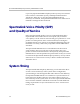
SpectraLink 8000 Telephony Gateway Administration Guide Up to forty SpectraLink 8000 Telephony Gateways may be connected to the LAN for a maximum capacity of 640 SpectraLink Wireless Telephones. When five or more SpectraLink 8000 Telephony Gateways are installed, the SpectraLink 8000 SVP Server must also be installed to manage the increased load.
SpectraLink Overview System Speed SpectraLink Wireless Telephones can operate up to 54 Mb/s in 802.11a and 802.11g modes, and up to 11 Mb/s in 802.11b and b/gmixed modes. In the b and b/g-mixed modes, if certain versions of legacy SpectraLink Wireless Telephones are used in the system, all handsets running in that mode will operate at the lowest common capability. System Components SpectraLink Wireless Telephones Employees can carry handsets to place and receive calls as they move throughout the building.
SpectraLink 8000 Telephony Gateway Administration Guide 8000 Telephony Gateway that works with telephone systems (CO, PBX, or Key Systems) with analog (loop start) ports. Access points Access points (APs) are supplied by third party vendors, APs provide the connection between the wired Ethernet LAN and the wireless (802.11) LAN. APs must be positioned in all areas where SpectraLink Wireless Telephones will be used.
SpectraLink Overview SpectraLink 8000 SVP Server The SpectraLink 8000 SVP Server manages call volume and speed. It is required in any system when five or more SpectraLink 8000 Telephony Gateways are connected to the LAN. With 40 SpectraLink 8000 Telephony Gateways cabled together, a single SpectraLink 8000 SVP Server supports 120 simultaneous handset calls. Multiple SVP Servers can be installed to maximize system capacity.
SpectraLink 8000 Telephony Gateway Administration Guide System Diagram Administrative computer Access point SpectraLink 8000 SVP Server Ethernet switch Wireless Telephones Access point SpectraLink 8000 Telephony Gateway optional SpectraLink 8000 Telephony Gateway Wireless POS SpectraLink 8000 Telephony Gateway SpectraLink 8000 Telephony Gateway SpectraLink 8000 Telephony Gateway Demarc block CAT 5 cable 25 pair cable Multiple phone cables Phone cable PBX Device supplied by Polycom desksets Fiv
SpectraLink Overview The Front Panel of the SpectraLink 8000 Telephony Gateway The SpectraLink 8000 Telephony Gateway's front panel contains the connections to other SpectraLink 8000 Telephony Gateways, the telephone system and LAN, as well as status LEDs.
SpectraLink 8000 Telephony Gateway Administration Guide 4: Timing Master 5: Lit if this gateway is the master gateway, used for timing only 8 = Conn A, Conn B: RJ-21 connector to the telephone cross-connect demarc block. Connector B is used only with four-wire interface Digital SpectraLink 8000 Telephony Gateways that work with the most common brands of telephone systems' (PBX or key systems) digital ports. 9 = PWR: Power jack that connects to the AC adapter supplying power to the system.
2 Installation and Configuration Steps Installation and configuration has several phases. In some cases, a separate person is responsible for each phase. It is important to coordinate the activities among the persons involved. The customer or vendor installs the APs per the Configuration Guide for the AP being used. This is normally done before the SpectraLink 8000 Telephony Gateway installation, but should be done before step 3 below.
3 Site Preparation As shown in the system diagram in the previous section, the SpectraLink 8000 Telephony Gateway is connected to both the Ethernet switch and the wired telephone system; the SpectraLink 8000 SVP Server is connected to the Ethernet switch only. The specifications covered here allow for great flexibility in physical placement of the components within stated guidelines. This unit must be installed by a service person familiar with the installation of electronic equipment.
SpectraLink 8000 Telephony Gateway Administration Guide wall. Four #8 x 3/4” panhead wood screws (or similar device) are required for each component. 20 • 10BaseT Cables: RJ-45 connector at each SpectraLink 8000 Telephony Gateway. Connection to Ethernet switch. • CAT 5 Cable: RJ-45 connector at the SpectraLink 8000 SVP Server. Connection to Ethernet switch. • Modem Cable: DB-9 female, null-modem cable. Required for initial setup of the SpectraLink 8000 Telephony Gateway and SVP Server.
Site Preparation LAN Requirements Network infrastructure The SpectraLink 8000 Telephony Gateway connects to your local area network (LAN). To provide adequate bandwidth and limit collisions, an Ethernet switch is required. The traffic between the SpectraLink 8000 Telephony Gateway and wireless LAN APs should be isolated as much as possible to avoid additional latency. The SpectraLink 8000 Telephony Gateway and APs must be on the same logical IP subnet.
SpectraLink 8000 Telephony Gateway Administration Guide IP multicast addresses are used by the SpectraLink i640 and 8030 Wireless Telephone. This requires that multicasting be enabled on the subnet used for the SpectraLink Wireless Telephones, SVP Server, and Telephony Gateways. Routers are typically configured with filters to prevent multicast traffic from flowing outside of specific domains.
4 Telephone Interface Configuration The customer or the customer's wire contractor is responsible for adhering to all local codes for wiring. Prepare Demarcation (Demarc) Blocks The SpectraLink 8000 Telephony Gateway is connected to the existing telephone system using RJ-21 connections. A SpectraLink 8000 Telephony Gateway is designed to operate with a specific interface to the telephone system: two-wire digital, two-wire analog, or four-wire digital. A four-wire system may require two demarc blocks.
SpectraLink 8000 Telephony Gateway Administration Guide your site will use administration by modem, this connection should be included in the wiring installation. 24 PN: 1725-36028-001_T.
Telephone Interface Configuration Install Telephone Demarc Blocks The demarcation blocks used to connect the telephone system to the Telephony Gateway should be installed on 3/4” telephone facility backboard. Although this manual uses 66-blocks as examples, any standard cross-connect blocks are acceptable.
SpectraLink 8000 Telephony Gateway Administration Guide Two-wire analog or digital demarc block The demarc block for the two-wire analog or digital interface should be wired as follows.
Telephone Interface Configuration Four-wire digital demarc block (Connector A) The four-wire digital interface requires two demarc blocks, one to Connector A and one to Connector B on the SpectraLink 8000 Telephony Gateway. They should be wired as follows.
SpectraLink 8000 Telephony Gateway Administration Guide Four-wire digital demarc block (Connector B) Line 1 RX Line 2 RX Line 3 RX Line 4 RX Line 5 RX Line 6 RX Line 7 RX Telephone Ports Note: RX denotes data received by the telephone system from Gateway Line 8 RX Line 9 RX Line 10 RX Line 11 RX Line 12 RX Line 13 RX Line 14 RX Line 15 RX Line 16 RX tip ring tip ring tip ring tip ring tip ring tip ring tip ring tip ring tip ring tip ring tip ring tip ring tip ring tip ring tip ring tip ring 25 PAIR MAL
5 Pre-Installation Verification Verify Pre-Installation Requirements Check the site to be sure pre-installation work has been completed correctly. This includes: • Location chosen for the SpectraLink 8000 Telephony Gateway is adequate and power is available. • APs are interoperable with SVP and coverage is adequate. • Telephone lines for the wireless devices are installed and properly terminated.
SpectraLink 8000 Telephony Gateway Administration Guide • Screws: Four, 3/4”, #8 panhead screws for each SpectraLink 8000 Telephony Gateway to be wall mounted. • Star Washers: When installing multiple SpectraLink 8000 Telephony Gateways, two per SpectraLink 8000 Telephony Gateway, to provide static protection. • ESD Bonding Straps: When installing multiple SpectraLink 8000 Telephony Gateways, one per SpectraLink 8000 Telephony Gateway, to provide static protection.
6 Install SpectraLink 8000 Telephony Gateway Mount to Rack or Wall The SpectraLink 8000 Telephony Gateways can be wall mounted either horizontally or vertically. Gateways may also be rack mounted in a standard 19-inch rack. A Rack Mount Kit must be purchased separately for a rack mount installation. To Mount Gateways… Horizontally Connector A is… Mount the Units… Clearance Between Gateways To the right side of the SpectraLink 8000 Telephony Gateway, with labels in correct position.
SpectraLink 8000 Telephony Gateway Administration Guide Mount the SpectraLink 8000 Telephony Gateway to rack The Rack Mount Kit is designed for mounting equipment in a standard 19-inch rack and should contain the following equipment: • Mounting plates: Two for each Gateway to be mounted. • Screws: Four rack mount screws for each Gateway to be mounted. Follow these steps to mount the Gateway to a rack: 1. Remove the corner screws from the Gateway. 2.
Install SpectraLink 8000 Telephony Gateway All system units must be grounded to a protective earth by means of the grounding stud located on the rear panel. Refer to the illustration below for recommended continuity connection. No more than 15 units may be grounded through one connection to the protective earth ground. Systems involving more than 15 units must be broken up into groups of 15 or fewer units with each group provided with an independent protective earthing conductor. PN: 1725-36028-001_T.
SpectraLink 8000 Telephony Gateway Administration Guide Installing Multiple SpectraLink 8000 Telephony Gateways If installing more than one SpectraLink 8000 Telephony Gateway, the ESD bonding strap(s) must be installed between adjacent Gateways. Mount Gateway 1. See directions for installing a single Gateway in previous section. Measure carefully to allow no more than 1/2” between Gateways. Drill holes and place screws. 2.
Install SpectraLink 8000 Telephony Gateway Install IPC cables To connect IPC cables on four or fewer SpectraLink 8000 Telephony Gateways (without a SpectraLink 8000 SVP Server): 1. Mount the SpectraLink 8000 Telephony Gateways. 2. Connect the IPC cable from the IPC OUT Port of the first unit to the IPC IN Port of the adjacent unit. 3. Repeat step 2 until all units are connected. The following illustration shows a horizontally mounted system, with SpectraLink 8000 Telephony Gateway number one at the bottom.
SpectraLink 8000 Telephony Gateway Administration Guide When installing a system with four or fewer SpectraLink 8000 Telephony Gateways and a SpectraLink 8000 SVP Server, no IPC cables are required. For this configuration, follow the directions for connecting five or more SpectraLink 8000 Telephony Gateways. Connect five or more SpectraLink 8000 Telephony Gateways To mount five or more SpectraLink 8000 Telephony Gateways: 1. Mount the SpectraLink 8000 Telephony Gateways on the backboard or rack. 2.
Install SpectraLink 8000 Telephony Gateway Use only the provided Class II AC Adapter with output 24V DC, 1A. For proper operation, all SpectraLink 8000 Telephony Gateways must be powered on and off at the same time. For installations with more than one SpectraLink 8000 Telephony Gateway, use an outlet strip with a built in power switch to allow SpectraLink 8000 Telephony Gateways to be turned on and off together. 2.
7 SpectraLink 8000 Telephony Gateway Administration Overview The SpectraLink 8000 Telephony Gateway(s) and wireless telephones are administered and maintained through a series of menu options for each SpectraLink 8000 Telephony Gateway in the system. The SpectraLink 8000 SVP Server has a separate set of menus that are covered in a separate document: SpectraLink 8000 SVP Server Administration Guide for SRP.
SpectraLink 8000 Telephony Gateway Administration Guide Administration Console. They are administered independently as covered in the Configuration Guide for the specific type of AP in use. 40 PN: 1725-36028-001_T.
SpectraLink 8000 Telephony Gateway Administration Overview SpectraLink 8000 Telephony Gateway Configuration Sequence This section covers the steps that must be taken to configure the SpectraLink 8000 Telephony Gateway for operation. The usual course of setup procedures will follow these general steps in the following order: 1. Configure the APs per the Configuration Guide for the type of APs in use at the site. Ensure the data rates are correctly set for your system design. 2.
SpectraLink 8000 Telephony Gateway Administration Guide to highlight Reset All Systems and press Enter. Respond with a Y to the reset prompt. 7. For each Gateway, assign handsets to telephone lines controlled by each SpectraLink 8000 Telephony Gateway per Chapter 13, Telephone Line Configuration. 8. For each Gateway (using Send All as indicated): Establish feature programming per Chapter 14 Features Programming Menu and the LinkPlus Interface Guide for your telephone system. 9.
SpectraLink 8000 Telephony Gateway Administration Overview Navigating through the Administration Console Screens Use the following keys to move around the Administration Console screens. To Perform this Function: Select function from menu Press: Use arrow keys to highlight selection, press Enter Display menu associated with highlighted field Enter: the Enter key will either display the options associated with an item or allow you to type an entry into the field.
8 Connecting to the SpectraLink 8000 Telephony Gateway For the initial configuration of each SpectraLink 8000 Telephony Gateway, you should have the Wireless Device Planning Worksheet(s) that was filled out during the installation of the system. There should be one for each SpectraLink 8000 Telephony Gateway.
SpectraLink 8000 Telephony Gateway Administration Guide 2. Run a terminal emulation program (such as HyperTerminal™) or use a VT-100 terminal with the following configuration: Bits per second: 9600 Data bits: 8 Parity: None Stop bits: 1 Flow control: None 3. Press Enter to display the SpectraLink 8000 Telephony Gateway login screen. 4. Enter the default login: admin and default password: admin. These are case sensitive.
Connecting to the SpectraLink 8000 Telephony Gateway If using a serial connection, only the SpectraLink 8000 Telephony Gateway that is connected via the serial cable is shown. 1. From the NetLink 8000 System menu, navigate to the Network Configuration screen and set the IP address. Note that the Allow Telnet Connections option must remain at the default Yes in order to access this SpectraLink 8000 Telephony Gateway via the LAN. 2. You may optionally change the default host name, if desired.
SpectraLink 8000 Telephony Gateway Administration Guide Configuration screen. Use the arrow keys to highlight Reset All Systems and press Enter. Respond with a Y to the reset prompt. Note that after IP addresses are established and the SpectraLink 8000 Telephony Gateways are functioning on the LAN, the S=Send All command can be used to send configuration information to every SpectraLink 8000 Telephony Gateway in your LAN. 5. Unplug the serial cable. 48 PN: 1725-36028-001_T.
Connecting to the SpectraLink 8000 Telephony Gateway Connecting via Telnet In addition to the serial connection described in the previous section, connection to the SpectraLink 8000 Telephony Gateway may be done via the network using Telnet. Once the IP addresses are configured, every SpectraLink 8000 Telephony Gateway is accessible through a connection to any SpectraLink 8000 Telephony Gateway.
SpectraLink 8000 Telephony Gateway Administration Guide The following settings use the US Robotics® Sportster® modem. Other modem models may be used, but the particular model’s settings will have to be adapted to conform to those listed in the following table. Configure modem internal settings (US Robotics Sportster) 1. Connect the modem to a PC using a standard modem cable. Plug the 9-pin connector into the RS-232 port on the PC, and the 25-pin connector into the modem’s port. 2.
Connecting to the SpectraLink 8000 Telephony Gateway Connect the modem Unplug the modem from the PC’s serial port and plug it into the SpectraLink 8000 Telephony Gateway. Connecting via Internal Modem An internal 2400-baud modem is built into the SpectraLink 8000 Telephony Gateway. Line one can be configured to connect via this modem. The modem is only used by Polycom Customer Service to assist in troubleshooting problems by remotely accessing the Gateway.
9 Main Menu The NetLink 8000 System menu provides a list of options for the maintenance of the SpectraLink 8000 Telephony Gateway and the handsets it supports. Menu Option System Status Function Provides status of SpectraLink 8000 Telephony Gateway and its communications links. Used to view the system operation and troubleshoot problem areas.
10 Network Configuration IP address and additional LAN settings are set and changed in the Network Configuration screen, available from the NetLink Wireless Telephone System menu. Scroll to remaining options: The options listed below with the arrow bullet ¾ are minimal settings required for SpectraLink 8000 Telephony Gateway functioning. Additional settings may be required by your system. Do not change PN: 1725-36028-001_T.
SpectraLink 8000 Telephony Gateway Administration Guide settings until you have studied this section and are familiar with the consequences any change will produce. When the settings marked with an arrow bullet ¾ are changed, the SpectraLink 8000 Telephony Gateway automatically goes into Maintenance Lock and prevents any new calls from starting. Resetting terminates any active calls and clears the Maintenance Lock.
Network Configuration correct setting from the DHCP server. The DHCP setting is only valid when the IP address is also acquired using DHCP. WINS servers: These setting are used for Windows Internet Name Services. Consult your system administrator for the correct settings. These can also be set to DHCP. This will cause the DHCP client in the gateway to attempt to automatically get the correct setting from the DHCP server. The DHCP setting is only valid when the IP address is also acquired DHCP.
SpectraLink 8000 Telephony Gateway Administration Guide Press Esc to return to the SpectraLink 8000 System menu. Note that resetting the SpectraLink 8000 Telephony Gateway(s) will terminate any calls in progress on the SpectraLink 8000 Telephony Gateway(s) being reset. All SpectraLink 8000 Telephony Gateways should be reset at the end of any maintenance procedure that requires any one SpectraLink 8000 Telephony Gateway to be reset either via Maintenance Lock or manually via Reset System.
11 Set or Change Password Passwords may be set uniquely for each SpectraLink 8000 Telephony Gateway. If this is done, each must be administered independently and the Send All command will not work. If Send All is to be utilized in your system, all passwords must be identical. Once all SpectraLink 8000 Telephony Gateways are on the LAN, a global password may be set.
SpectraLink 8000 Telephony Gateway Administration Guide If you forget a password, call Polycom Customer Service for assistance. In order for Send All to function across all SpectraLink 8000 Telephony Gateways, all passwords must be identical. If one or more SpectraLink 8000 Telephony Gateways are configured with different passwords, the Send All command will not configure them and they must be administered independently. 60 PN: 1725-36028-001_T.
12 SpectraLink 8000 Telephony Gateway Configuration Select Gateway Configuration from the NetLink Wireless Telephone System menu. Scroll to remaining option: The options listed below with the arrow bullet ¾ are minimal settings required for SpectraLink 8000 Telephony Gateway functioning. Do not change settings until you have studied this section and are familiar with the consequences any change will produce. PN: 1725-36028-001_T.
SpectraLink 8000 Telephony Gateway Administration Guide Where available, S=Send All may be used to send identical configuration settings to every other SpectraLink 8000 Telephony Gateway in the system. ¾ Telephone Switch Type: Press Enter to change this field. From the sub-menu of PBX types, select the telephone switch type you are using.
SpectraLink 8000 Telephony Gateway Configuration Telephony Gateway. Software updates received from Polycom must be placed in this location. See section 18, Software Maintenance, for more information. When the handset is turned on, it checks this source for confirmation that it is running the correct software version. If there is any discrepancy, the handset will download the software that resides in this source location.
SpectraLink 8000 Telephony Gateway Administration Guide The SpectraLink 8000 Telephony Gateway monitors the condition of any SpectraLink 8000 SVP Server(s) on the system. In a single SpectraLink 8000 SVP Server system, when the SVP Server goes into Maintenance Lock, the Telephony Gateway will also lock and set an alarm. No new calls will be allowed but calls in progress will not be affected.
SpectraLink 8000 Telephony Gateway Configuration Reset the SpectraLink 8000 Telephony Gateway Note that resetting the SpectraLink 8000 Telephony Gateway(s) will terminate any calls in progress on the SpectraLink 8000 Telephony Gateway(s) being reset. All SpectraLink 8000 Telephony Gateways should be reset at the end of any maintenance procedure that requires any one SpectraLink 8000 Telephony Gateway to be reset either via Maintenance Lock or manually via Reset System.
13 Telephone Line Configuration Telephone line configuration is performed after the initial SpectraLink 8000 Telephony Gateway installation is complete and the Gateway is configured. The configuration procedure associates a handset with its telephone port in the SpectraLink 8000 Telephony Gateway. For the line configuration of handsets, please have the handsets to be configured and the Wireless Device Planning Worksheet(s).
SpectraLink 8000 Telephony Gateway Administration Guide 1. Navigate to the NetLink Wireless Telephone System menu for the SpectraLink 8000 Telephony Gateway that serves the port to be configured. Select Telephone Line Configuration. 2. Enter the following information for each assigned line. Use the arrow keys to navigate through the fields. MAC Address: The MAC address is printed on the sticker underneath the battery on the handset.
Telephone Line Configuration A handset may be associated with one and only one telephone line. The same MAC address may not be assigned to two or more telephone lines. Deleting a Handset To delete a handset from the SpectraLink 8000 Telephony Gateway configuration: 1. Navigate to the NetLink Wireless Telephone System menu of the SpectraLink 8000 Telephony Gateway that serves the port for the line being used by the handset. Select Telephone Line Configuration. 2.
14 Features Programming Menu Two basic types of wired telephone systems exist—analog and digital. Both types offer special features such as hold, transfer, conference, camp on, and speed dial. In both types of systems, these features are activated in a telephone by pressing a series of keys or a single programmed button on a deskset.
15 Feature Programming (no Softkeys) If your system is utilizing any SpectraLink Wireless Telephones that do not have softkeys (PT800 series or earlier), Feature Programming is used to allow these handsets to access system features. Mute and optional OAI (Open Application Interface) must be programmed in the Feature Programming screen for both analog and digital systems. In digital systems, feature programming is done in the PBX.
SpectraLink 8000 Telephony Gateway Administration Guide Navigate to the NetLink Wireless Telephone System menu for the SpectraLink 8000 Telephony Gateway and select Feature Programming. A screen similar to the following displays: Programming Digital PBX Features The numbers and symbols along the left side of the screen indicate which number or digit key is being pressed after the FCN key to activate the feature. 1. Navigate to key 1 and type MUTE. 2.
Features Programming (no Softkeys) you change them, be sure to enter the corresponding changes in the Menu Programming screen in the next section. Function Key FCN+1 Feature Mute FCN+2 Xfer FCN+3 Conn FCN+4 Conf FCN+5 Fwd FCN+6 Redial FCN+7 Pick FCN+8 Camp FCN+9 Exit Menus Key Sequence MUTE (Leave Blank) FCN+0 FCN+* FCN+# Consult your wired telephone system documents for the key sequence that matches the feature in the above table. Blank cells are provided for your data.
SpectraLink 8000 Telephony Gateway Administration Guide Programming the ADMIN Feature The ADMIN option allows the system administrator to add and delete handsets via another handset, rather than via the SpectraLink 8000 Telephony Gateway. Any function key sequence may be programmed to ADMIN by typing ADMIN next to the desired key.
16 Menu Programming (no softkeys) If your system is utilizing any SpectraLink Wireless Telephones that do not have softkeys (PTB800 series or earlier), Menu Programming is used to enable these handsets to display a list of system features that have been programmed for end user access. The handset displays a menu of functions when the FCN key is pressed.
SpectraLink 8000 Telephony Gateway Administration Guide • For analog interfaces, the features defined for the custom menus should match the features programmed in the Feature Programming screen. For example, if you have defined FCN 2 on Feature Programming as Xfer, then you should also define FCN 2 on Menu Programming as Xfer. • For digital interfaces, the features defined for the custom menus should match the programming assigned through the PBX.
Features Programming (no Softkeys) 4. Repeat for each menu as needed. PN: 1725-36028-001_T.
17 Softkey and Shortcut Key Programming The softkeys on the SpectraLink e340/h340/i640 and 8020/8030 Wireless Telephones enable quick access to system features. The softkey programming screen establishes the correspondence between the PBX features, the softkeys, and the shortcut keys. There are 16 possible features displayed in the four levels of the softkey function display area. The default softkeys are at level 0 (zero).
SpectraLink 8000 Telephony Gateway Administration Guide Sample screen: Scroll to remaining options: The Action column indicates that the handset will perform the corresponding function of the emulated desk set. Action field entries are described in the table on the next page. The Menu Label is a description of the feature. The Softkey Label is the up to four-letter feature abbreviation that is displayed on the handset.
Softkey and Shortcut Key Programming Speakerphone softkey programming (SpectraLink 8020/8030 only) The SpectraLink 8020/8030 Wireless Telephones have an internal speakerphone which is activated through a softkey. Polycom recommends programming Level 0, softkey A for the speakerphone as that position matches the standby position the handset automatically assigns to the speakerphone. The speakerphone softkey will be blank on the e340/h340/i640 handsets.
SpectraLink 8000 Telephony Gateway Administration Guide Use this table to develop your own programming correspondence: Level 0 Softkey A Shortcut Menu Label Softkey Label Action B C D 1 A B C D 2 A B C D 3 A B C D 84 PN: 1725-36028-001_T.
18 Software Maintenance The SpectraLink 8000 Telephony Gateways and the wireless telephones use proprietary software programs written and maintained by Polycom Corporation. The software versions that are running on the system components can be displayed via the System Status screen. Downloads for the SpectraLink 8000 Telephony Gateway are available from http://www.polycom.com/usa/en/support/voice/wifi/spectralink_8000_telephony.html.
SpectraLink 8000 Telephony Gateway Administration Guide pd14udsp.bin pd14csp.bin pi1400sp.bin pd14odsp.bin slnk_cfg.cfg SpectraLink 8020/8030 Wireless Telephones Automatic from SpectraLink 8000 Telephony Gateway or TFTP Server*** *** as set in the Gateway Configuration screen, WT TFTP Download Master, IP address. SpectraLink 8000 SVP Server Load the updates onto the TFTP server and reboot the SpectraLink 8000 SVP Server. SVP100.
Software Maintenance When using FTP, use a host system to connect to a remote system. In this example, the host is the client and the server is the Telephony Gateway. The “put” command means to copy the files from the host to the remote system. The “get” command means to copy the files from the remote system to the host. Note that FTP commands vary with the program being used. Use the following steps as a general guide but be aware that your FTP program may use different terms to describe the procedure.
SpectraLink 8000 Telephony Gateway Administration Guide Updating Wireless Telephone Software SpectraLink handsets allow over-the-air transfer of software updates from the SpectraLink 8000 Telephony Gateway or designated TFTP server to the handsets. The downloader function in the handset checks its software version every time the handset is turned on. If there is any discrepancy in the functional code (pdt02c.bin or pft02c.bin or pd11spc.bin or pdt06c.bin) or the image (phintl.bin or phintl24.
Software Maintenance Download failure or recovery messages The following display messages indicate a failure or recovery situation during the download process. Message Server Busy Description Handset is attempting to download from a Download Master that is busy downloading other phones and refusing additional downloads. The handset will automatically retry the download every few seconds. TFTP ERROR(x):yy A failure has occurred during the TFTP download of one of the files.
SpectraLink 8000 Telephony Gateway Administration Guide 3. At the FTP prompt, type binary. A confirm message will display. 4. Use Get to backup the files and Put to restore files. Backup: At the FTP prompt, use the get command to transfer the required files from the SpectraLink 8000 Telephony Gateway to the server: get config.bin. Restore: At the FTP prompt, use the put command to transfer the required files from the server to the SpectraLink 8000 Telephony Gateway: put config.bin.
19 Troubleshooting via the System Status Menu Troubleshooting requires full information about the components of the SpectraLink 8000 System and the larger system, which includes both the host telephone system and the LAN. SpectraLink 8000 Telephony Gateways provide a “window” into the functioning of the various wireless components via the System Status Menu.
SpectraLink 8000 Telephony Gateway Administration Guide Access Point Status: Shows information about the APs that have been utilized by the handsets. Error Status: Displays alarm and error message information. Network Status: Displays information about the Ethernet network to which the SpectraLink 8000 Telephony Gateway is connected. Telephone Line Status: Displays information about the PBX lines to which the SpectraLink 8000 Telephony Gateway is attached and the handsets associated with these lines.
Troubleshooting via the System Status Menu Access Point Status During a call, handsets send information about their APs to the SpectraLink 8000 Telephony Gateway. The SpectraLink 8000 Telephony Gateway maintains information on the last 16 APs on which it has received reports and displays this information on the Access Point Status screen. Your wireless LAN vendor, and/or Polycom Customer Support will use the data on this screen to troubleshoot AP problems.
SpectraLink 8000 Telephony Gateway Administration Guide Last Heard and System Uptime indicates that the AP has not been used recently which might indicate that there has been a break in communications. System Uptime: Is the time elapsed since the SpectraLink 8000 Telephony Gateway was last reset or power cycled. This indicator allows you to check AP activity against SpectraLink 8000 Telephony Gateway functionality.
Troubleshooting via the System Status Menu The tables on the following pages display the list of alarm types, display messages, and description of the error. Alarm Config Message GW software version difference Error Description Conflicting software versions on two SpectraLink 8000 Telephony Gateways Action Upgrade the down rev. Config No IP address No IP address set in configuration Set IP address for SpectraLink 8000 Telephony Gateway.
SpectraLink 8000 Telephony Gateway Administration Guide Alarm DAA Message PBX table unavailable Error Description Bad software load on SpectraLink 8000 Telephony Gateway Action Call Polycom Customer Service. DAA PBX type unavailable Bad software load on SpectraLink 8000 Telephony Gateway DAA DAA type Mismatch Installed PBX interface cannot be used to attach to the specified PBX. Change the specified PBX or replace the SpectraLink 8000 Telephony Gateway with a model that supports the desired PBX.
Troubleshooting via the System Status Menu Alarm Line Sync Message Line [XX] out of sync (where XX is 1-16) Error Description The line from the host telephone system is not communicating with the SpectraLink 8000 Telephony Gateway. Action Check cabling from telephone system to SpectraLink 8000 Telephony Gateway. Check PBX type to be sure it is correctly configured. CT Bootload unavailable Bad software load on SpectraLink 8000 Telephony Gateway Call Polycom Customer Service.
SpectraLink 8000 Telephony Gateway Administration Guide Alarm Message Error Description Action Note: Radio alarms usually indicate internal software errors. Usually there will be no external indication of a problem. 1 Call Polycom Customer Service.
Troubleshooting via the System Status Menu Network Status The SpectraLink 8000 Telephony Gateway is connected to the Ethernet network, referred to as the LAN or Local Area Network. The information about that connection is provided through the Network Status screen. From the System Status Menu, select Network Status. The screen displays information about the Ethernet network. This information can help troubleshoot network problems. A sample screen is displayed here.
SpectraLink 8000 Telephony Gateway Administration Guide The rest of the display is a table of Ethernet statistics. The Pkts and UserPkts columns list the count of Ethernet packets received or transmitted. The Bytes column is the count of bytes received or transmitted during the amount of time indicated by Stats Time. Data is transmitted over the SpectraLink 8000 System by proprietary technology developed by Polycom Corporation.
Troubleshooting via the System Status Menu Missed Slots: Occurs when the SpectraLink 8000 Telephony Gateway does not have sufficient time to process audio. This number should always be 0 or 1. Buffer Overflow: Number of times Ethernet controller received more packets than it had buffers to store them. Indicates extreme traffic. Telephone Line Status Each SpectraLink 8000 Telephony Gateway associates handsets with lines from the host telephone system (PBX) as configured in the system setup.
SpectraLink 8000 Telephony Gateway Administration Guide Name: Person or name associated with the line for identification purposes. Extension: Extension number associated with the line for identification purposes. Status: Status of the lines from the host telephone system (PBX) to the SpectraLink 8000 Telephony Gateway. In Sync: Indicates there is communication between the SpectraLink 8000 Telephony Gateway and the PBX.
Troubleshooting via the System Status Menu WT MAC: The MAC address of the handset. Current AP: The MAC address of the AP the handset is using or last used. If the handset is not checked in, the SpectraLink 8000 Telephony Gateway will display ‘none’. The handset computes the “rate” for the following statistics by calculating the number to increase quickly when retries begin. As retries lessen to zero and the transmissions become more reliable, the number peaks and decreases slowly.
SpectraLink 8000 Telephony Gateway Administration Guide Num Calls: The number of currently active calls on the SpectraLink 8000 Telephony Gateway. Max Simul Calls: The maximum number of simultaneous active calls on the SpectraLink 8000 Telephony Gateway. Software Version Each SpectraLink 8000 Telephony Gateway and wireless telephone runs Polycom’s proprietary software that is controlled and maintained through versioning.
20 Wireless Device Planning Worksheet Copy and complete this worksheet to track parameters for each SpectraLink 8000 Telephony Gateway. SpectraLink 8000 Telephony Gateway Hostname: ___________________________________________________ MAC: ____________________________________ Subnet Mask: ________________________ _____________________________ IP Address: __________________________________ ______ Wireless Telephones per AP: _________________ ________________________________ Gateway Port 1 Dialing Ext.
SpectraLink 8000 Telephony Gateway Administration Guide 14 15 16 106 PN: 1725-36028-001_T.
Safety Notices Important Safety Information Follow these general precautions while installing telephone equipment: PN: 1725-36028-001_T.doc • Never install telephone wiring during a lightning storm. • Never install telephone jacks in wet locations unless the jack is specifically designed for wet locations. • Never touch uninsulated telephone wires or terminals unless the telephone line has been disconnected at the network interface. • Use caution when installing or modifying telephone lines.
Index A F Access point Configuration ...................................................39 Description........................................................12 Status .................................................................87 Administration Console Navigation..................42 Alarms ....................................................................88 Feature Programming, configuration of............69 FTP Procedure.......................................................
SpectraLink 8000 Telephony Gateway Administration Guide Description........................................................10 T Telephone Line Status ..........................................95 Telephone Lines, configuration of......................63 Telephone System, connecting to .......................23 Telnet ......................................................................46 Time format ...........................................................88 U W Wireless Device Planning Worksheet ....