SpectraLink 8000 SVP Server SVP100, SVP020, SVP010 Administration Guide for SIP July 2008 Edition 1725-36033-001 Version C
SpectraLink 8000 SVP Server: Administration Guide for SIP Trademark Information Notice Polycom® and the logo designs SpectraLink® LinkPlus Link NetLink SVP Are trademarks and registered trademarks of Polycom, Inc. in the United States of America and various countries. All other trademarks used herein are the property of their respective owners. Polycom, Inc. has prepared this document for use by Polycom personnel and customers.
About This Document This document explains how to configure and maintain one or more SpectraLink 8000 SVP Servers (models SVP100, SVP020, SVP010) within IP telephony environments. Polycom Model Numbers This document covers the following registered model number: SVP100 Related Documents SpectraLink 8020/8030 Wireless Telephone: Administration Guide for SIP (1725-36038-001) Available at. http://www.polycom.com/usa/en/support/voice/wi-fi/wi-fi.
SpectraLink 8000 SVP Server: Administration Guide for SIP Customer Support Polycom wants you to have a successful installation. If you have questions please contact the Customer Support Hotline at (800) 775-5330. The hotline is open Monday through Friday, 6 a.m. to 6 p.m. Mountain time. For Technical Support: technicalsupport@polycom.com For Return Material Authorization: rmacoordinator@polycom.com For Knowledge Base: http://www.polycom.com/usa/en/support/voice/voice.
Contents 0 About This Document ................................................................3 Polycom Model Numbers..................................................................3 Related Documents.............................................................................3 Customer Support...............................................................................4 Icons and Conventions.......................................................................
SpectraLink 8000 SVP Server: Administration Guide for SIP The NetLink SVP-II System Menu .................................................22 Network Configuration....................................................................23 SendAll .........................................................................................24 SVP Server Configuration................................................................26 SVP-II Mode............................................................................
1 SpectraLink 8000 SVP Server Overview The SpectraLink 8000 SVP Server is an Ethernet LAN device that works with access points (APs) to provide QoS on the wireless LAN. Voice packets to and from the SpectraLink 8000 Wireless Telephones are intercepted by the SVP Server and encapsulated for prioritization as they are routed to and from an IP telephony server.
SpectraLink 8000 SVP Server: Administration Guide for SIP SpectraLink 8000 SVP Server Models The SVP Server is available in three models. Which model is selected for your facility depends on current and expected capacity. All SVP Servers within a subnet must be the same model type. • SVP100: Serves 80 calls simultaneously. • SVP020: Serves 20 powered-on handsets. • SVP010: Serves 10 powered-on handsets. See the following capacity tables for multiple SVP Server system capacities.
SpectraLink 8000 SVP Server Overview telephones, and between the SVP Server and the PBX (or other far-end device). SVP Server availability A SpectraLink handset registers to a single SVP Server the first time it is powered on. Once the handset has contacted this Registration Server, it obtains a list of all SVP Servers in the system. The handset then maintains this list in non-volatile memory and updates it as needed.
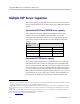
SpectraLink 8000 SVP Server: Administration Guide for SIP Multiple SVP Server Capacities The system capacity of each SVP Server model is shown in the tables below. Note that SVP Server models may not be combined within one subnet. SpectraLink SVP010 and SVP020 Server capacity The system capacity of the SVP010 and SVP020 is measured by number of powered-on handsets. If this number exceeds the maximum, the handset that cannot be served will display an error and will not connect to the SVP Server.
SpectraLink 8000 SVP Server Overview possible installed handsets figures are approximate and meant as a guideline and not as an absolute recommendation for any facility.
SpectraLink 8000 SVP Server: Administration Guide for SIP Notes on System Configuration In an IP system using subnets to differentiate telephony areas, each subnet must have its own APs. Each subnet may require an SVP Server to maintain voice quality, but this depends on traffic volume and router capacity. Multiple SVP Server environments are those which have more than one SVP Server. SVP Server models may not be combined within one subnet.
SpectraLink 8000 SVP Server Overview System Diagram The following diagram shows multiple SVP Servers residing on a network with an IP telephony gateway and IP telephony server, wireless LAN APs, and Ethernet switch: SpectraLink 8000 SVP Server SpectraLink 8000 SVP Server Access point TFTP server SpectraLink 8000 SVP Server (showing optional multiple SVP Servers) Ethernet switch SpectraLink Wireless Telephones Access point IP gateway Optional Wireless POS PSTN or PBX SpectraLink Wireless Telephones Spe
SpectraLink 8000 SVP Server: Administration Guide for SIP System Components SpectraLink e340/h340/i640 and 8020/8030 Wireless Telephones Employees can carry wireless telephones to make and receive calls as they move throughout the building. The wireless telephones are to be used on-premises; they are not cellular or satellite phones.
SpectraLink 8000 SVP Server Overview network traffic is restricted to those segments that are directly involved in the communication. Installation of a network router is recommended in larger networks, where there may be significant network traffic not related to the wireless LAN. A router will isolate the wireless LAN from the associated wired LAN so that they are not impacted by each others’ traffic.
SpectraLink 8000 SVP Server: Administration Guide for SIP The Front Panel of the SVP Server The SVP Server’s front panel contains ports to connect to power, the LAN, and to an administrative computer via an RS-232 port. Status LEDs supply information about the SVP Server’s functioning. 1 L N K O K A C T C O L NETWORK E R R O R 2 3 4 5 PWR Status RS-232 RS-232 Port: male DB-9 connector (DTE) used for RS-232 connection to a terminal, terminal emulator, or modem for system administration.
2 Installing the SpectraLink 8000 SVP Server As shown in the system diagram, the SVP Server is connected to the Ethernet switch. The specifications covered here allow for great flexibility in physical placement of the components within stated guidelines. See the Configuration and Administration document for your vendor’s IP system for information on LAN requirements, network infrastructure and IP addressing.
SpectraLink 8000 SVP Server: Administration Guide for SIP Locate the SVP Server The SVP Server measures approximately 4 x 12.5 x 7 inches, and weighs about five pounds. The unit can be wall- mounted, vertically or horizontally, over ¾" plywood. The SVP Server can also be rackmounted using a rack- mount kit (sold separately). Locate the SVP Server in a space with: • Sufficient backboard mounting space (for wall mount) and proximity to the LAN access device (switched Ethernet hub) and power source.
Installing the SpectraLink 8000 SVP Server Mount the SVP Server to a wall The SVP Server can be mounted either horizontally or vertically. To mount the SVP Server to a wall: 1. Using a 1/8-inch drill bit, drill four pilot holes, on 1.84-inch by 12.1-inch centers (approximately equivalent to 1-13/16” by 12-1/8”). 2. Insert the #8 3/4-inch screws in the pilot holes and tighten, leaving a 1/8-inch to 1/4-inch-gap from the wall.
SpectraLink 8000 SVP Server: Administration Guide for SIP Connect SVP Server to LAN Using a Cat. 5 cable, connect the NETWORK port on the SVP Server to the connecting port on the Ethernet switch. Connect power 1. Once the units have been properly grounded, connect the power plug from the AC adapter to the jack labeled PWR on the SVP Server. Use only the provided Class II AC Adapter with output 24V DC, 1A. 2. Plug the AC adapter into an 110V AC outlet to apply power to the SVP Server. 3.
3 Configuring the SpectraLink 8000 SVP Server During initial setup of the SVP Server the IP address is established and the maximum number of active calls per AP is set. Optionally, you may enter a hostname and a location for software updates via TFTP. Connecting to the SVP Server The initial connection to the SVP Server must be made via a serial connection to establish the SVP Server’s IP address. After the IP address is established, connection to the SVP Server may be done via the network using telnet.
SpectraLink 8000 SVP Server: Administration Guide for SIP Connecting via telnet Telnet can only be used after the SVP Server’s IP address is configured. The telnet method of connection is used for routine maintenance of the SpectraLink Server for both local and remote administration, depending on your network. To connect via telnet, run a telnet session to the IP address of the SVP Server. Once you connect and log in, the NetLink SVP-II System menu displays.
Configuring the SpectraLink 8000 SVP Server Network Configuration Allows you to set network configuration options, including IP address and hostname. Change Password Allows you to change the password for SVP Server access. Network Configuration The IP address and other network settings are established via the Network Configuration screen. This is also where you may optionally establish a hostname and enter the IP address of the location of any software updates you may obtain from Polycom.
SpectraLink 8000 SVP Server: Administration Guide for SIP SendAll In an IP system with multiple SVP Servers, the SendAll option is provided to speed configuration and to ensure identical settings. The S=SendAll option allows you to send that configuration parameter to every SVP Server on the LAN. SendAll can only be used after the IP address is established on EACH SVP Server via the serial connection.
Configuring the SpectraLink 8000 SVP Server Subnet Mask The network administrator must define the subnet mask. Default Gateway The IP address of a router on the local subnet. SVP-II TFTP Download Master This entry indicates the source of software updates for the SVP Server. See Chapter 5 Software Maintenance for more information. Valid source location entries are: • NONE: disables. • IP Address: The IP address of a network TFTP server that will be used to transfer software updates to the SVP Server.
SpectraLink 8000 SVP Server: Administration Guide for SIP Syslog Server Logging can be set to Syslog or NONE. If Syslog is set, a message is sent to the syslog server when an alarm is triggered. Disable Telnet service Prevents Telnet access into the SVP Server. Reset the SVP Server for the change to take effect. Upon reset the Telnet protocol server is not started. The SVP Server must be reset in order to set the configuration options.
Configuring the SpectraLink 8000 SVP Server SVP-II Mode Defaults to SpectraLink IP for an IP environment. Press Enter to select and the screen is immediately redrawn with additional options for the IP environment. The following options must be configured: Phones per Access Point AP specifications are detailed in the Configuration Notes for each brand and type. Refer to these notes when entering the number of simultaneous calls supported for your type. 802.
SpectraLink 8000 SVP Server: Administration Guide for SIP First Alias IP Address/Last Alias IP Address The SVP Server uses an IP address when acting as a proxy for the wireless telephone. Therefore, one alias IP address is required for every installed Wireless Telephone. These IP addresses must be entered as a range and must be assigned solely for this purpose. When multiple SVP100 Servers are installed, a different range must be configured in each SVP Server.
Configuring the SpectraLink 8000 SVP Server that the administrator cannot change this option. It is automatically set by the system. Reset the system at exit to clear Maintenance Lock. Inactivity Timeout (min) Set the number of minutes the administrative module can be left unattended before the system closes it. This number can be from 1 to 100. If it is set to zero (0), the administrative module will not close due to inactivity. QoS Configuration Select this option to set the DSCP tags.
SpectraLink 8000 SVP Server: Administration Guide for SIP QoS Configuration DSCP tags set packet priorities for QoS. DSCP Tag DSCP (Differentiated Services Code Point) is a QoS mechanism for setting relative priorities. Packets are tagged with a DSCP field in the IP header for type of service. The decimal value may be set as a number from 0-63 and may be different for each traffic class listed on the screen. • Administration tags set the priority for telnet, TFTP, and other administrative traffic.
Configuring the SpectraLink 8000 SVP Server When forwarding packets, the SVP Server shall always overwrite the received DSCP value. The final DSCP tag for packets in each of the traffic classes are assigned a DSCP value based on the following rules. (Please see table on next page.) • If both Administration and the Traffic Class setting is Default, the Default value as shown in the table below will be used.
SpectraLink 8000 SVP Server: Administration Guide for SIP Change Password If desired, the password to access the SVP Server may be changed. A password must meet the following requirements: • It must be more than four characters, but cannot exceed 16 characters. • The first character must be a letter. • Numbers or letters are allowed. • No dashes, spaces, or punctuation marks, etc. are allowed. Select Change Password from the main menu.
4 Swapping/Adding/Deleting SVP Servers Whenever an SVP Server is removed from the system, wireless telephones that are using the SVP Server will be affected and calls may be lost. If the removal of the SVP Server is intentional, the administrator should lock and idle the system prior to removing an SVP Server. Adding an SVP Server A new SVP Server is detected within two seconds of being added to the system (booted/configured/connected).
SpectraLink 8000 SVP Server: Administration Guide for SIP SVP Server Failure If an SVP Server becomes unable to manage calls, any handset in an active call using that Server will lose the call. However, upon initiating a new call, the handset will locate another Server and will be able to make new calls. 34 PN: 1725-36033-001_C.
5 Software Maintenance The SVP Server uses proprietary software programs written and maintained by Polycom Corporation. The software versions that are running on the system components can be displayed via the System Status screen. You may obtain information about software updates from Polycom or its authorized dealer. At startup the SVP Server uses TFTP to check the software version it is running against the version in the TFTP location.
6 Troubleshooting via System Status Menu Information about system alarms, and network status displays on various screens accessed through the System Status Menu screen, which is opened from the main menu of the SVP Server. See the previous sections for directions on how to connect to the SVP Server and navigate to the System Status Menu. Error Status - Displays alarm and error message information. Network Status - Displays information about the Ethernet network to which the SVP Server is connected.
SpectraLink 8000 SVP Server: Administration Guide for SIP system function and to troubleshoot areas that may be experiencing trouble. Error Status The Error Status screen displays any alarms that indicate some system malfunction. Some of these alarms are easily remedied and others require a call to Polycom’s Customer Support Department. From the System Status Menu, select Error Status. The screen displays active alarms on the SVP Server.
Troubleshooting via System Status Menu Network Status The SVP Server is connected to the Ethernet network, referred to as the LAN or Local Area Network. The information about that connection is provided through the Network Status screen. From the System Status Menu, select Network Status. The screen displays information about the Ethernet network. This information can help troubleshoot network problems. A sample screen is displayed here. Ethernet Address – MAC address of the SVP Server (hexadecimal).
SpectraLink 8000 SVP Server: Administration Guide for SIP RX – Ethernet statistics concerning the received packets during System Uptime.
Troubleshooting via System Status Menu Software Version The SVP Server and wireless telephones utilize Polycom Corporation’s proprietary software that is controlled and maintained through versioning. The Software Version screen provides information about the version currently running on the SVP Server. This information will help you determine if you are running the most recent version and will assist Polycom engineering and/or customer support in troubleshooting software problems.
SpectraLink 8000 SVP Server: Administration Guide for SIP The table below shows the description, major version numbers, and filenames of the files that are provided when downloading updates. Name Table of contents Major Version Number 173 Filename svp100.toc Functional code 174 zvmlinux File system 175 flashfs The minor version numbers for these three files must all match, as they do in the screen example (17x.024). 42 PN: 1725-36033-001_C.
Safety Notices WARNING: Changes or modifications to this equipment not approved by SpectraLink Corporation may cause this equipment to not comply with part 15 of the FCC rules and void the user’s authority to operate this equipment. WARNING: SpectraLink products contain no user-serviceable parts inside. Refer servicing to qualified service personnel. IMPORTANT SAFETY INFORMATION Follow these general precautions while installing telephone equipment: PN: 1725-36033-001_C.
Index Location.............................................................18 Rack mounting .................................................18 Wall mounting..................................................19 A Access point, description .....................................14 Administration of .................................................21 Alarms ....................................................................40 C Configuration Initial setup ......................................................