PC/MP/USCvr 6/16/99 4:10 PM Page 1 ViewStation 128/512/MP ™ USER’S GUIDE
Polycom, Inc. © 1999 Polycom Inc. All rights reserved. No part of this document may be reproduced or transmitted in any form or by any means, electronic or mechanical, for any purpose, without the express written permission of Polycom, Inc. Under the law, reproducing includes translating into another language or format. As between the parties, Polycom, Inc. retains title to, and ownership of, all proprietary rights with respect to the software contained within its products.
Limitation of Remedies and Damages Polycom, Inc., its agents, employees, suppliers, dealers and other authorized representatives shall not be responsible or liable with respect to the product or any other subject matter related thereto under any contract, negligence, strict liability or other theory for any indirect, incidental, or consequential damages, including, but not limited to loss of information, business, or profits.
Changes or modifications not expressly approved by Polycom could void the user's authority to operate this equipment. 1. This equipment complies with Part 68 of the FCC Rules. On the bottom of this equipment is a label that contains, among other information, the FCC registration number and Ringer Equivalence Number (REN) for this equipment. If requested, provide this information to your telephone company. 2.
Underwriters’ Laboratories’ Statement The system is intended to be powered by a Class 2 power supply 5V@4.5A, 12V@1.5A. Omnitel Statement THE SOFTWARE PROGRAMS CONTAINED OR DESCRIBED HEREIN ARE CONFIDENTIAL INFORMATION AND PROPRIETARY PRODUCTS OF POLYCOM OR ITS LICENSORS. VideoServer Statement Buyer shall not sublicense or otherwise distribute any of the Subject Programs except to End Users and/or resellers who have entered into a Sublicense Agreement.
Table of Contents Getting Started What’s In the Box? .............................................................................................................. 11 The Remote Control ............................................................................................................. 13 The Microphone Pod ............................................................................................................ 13 What You Need to Get Started ....................................................
Table of Contents Setting Camera Presets ........................................................................................................ 44 Mirroring the Camera Positions .................................................................................... 45 Automatic Voice Tracking ................................................................................................... 45 Tracking to Camera Presets ........................................................................................
Table of Contents System Information ViewStation Diagnostics ...................................................................................................... 85 Network Statistics ......................................................................................................... 86 Advanced Network Statistics ........................................................................................ 87 Call Status ....................................................................................
Table of Contents IMUX Information ...................................................................................................... 122 Upgrading Your ViewStation 512 to an MP ..................................................................... 122 Troubleshooting ISDN Information ISDN Switches ................................................................................................................... 131 ISDN Errors ...........................................................................
Getting Started Thank you for purchasing the ViewStation! You will soon discover that videoconferencing is as easy as talking on the telephone. The ViewStation is the most easy-to-use videoconferencing unit on the market today. The QuickStart booklet that came with your unit shows you how to connect the ViewStation. This manual will explain all the features common to the ViewStation 128, 512 and MP.
Getting Started 12 • Remote control • User’s Guide • QuickStart booklet • ReadMe First document • Package labeled “Required Cables” that contains three cables • Package labeled “Optional Equipment Cables” that contains eight cables • Miscellaneous package that contains a hook and loop cable tie, adhesive dots, and three AAA batteries. • The ViewStation 512 and MP packages include additional components that are necessary for the connection of multiple ISDN lines.
Getting Started The Remote Control The remote control that came with your ViewStation is an integral part of the unit. It works the same way as the remote for your television at home. You’ll be using it to highlight and select icons that appear on the monitor, configure your address book, move your camera, adjust the volume, place video calls, etc.
Getting Started Television Monitors You can use any size S-Video or composite television monitor with the ViewStation. The size of the monitor should be proportional to the size of the room in which the ViewStation resides. You can further enhance your videoconference by connecting two monitors to your ViewStation, one for video and another for displaying graphics. Power Supply The ViewStation power supply supports line voltages between 100V and 240V or 50Hz and 60Hz.
Getting Started Setting Up Your ViewStation Connecting the ViewStation is easy. The cable connectors are color-coordinated with the corresponding connectors on the back of the ViewStation. To hook up your ViewStation, use your QuickStart booklet as a guide and follow these steps: 1. Place the ViewStation unit on top of the monitor as shown below. Make sure the front lip of the unit hangs over the edge of the monitor. 2.
Getting Started 16 3. Connect the various cables to the back of your ViewStation. For more details, see your QuickStart booklet. 4. Connect any extra equipment, such as an additional television monitor, a VCR, laptop, LAN, telephone, or document camera, to the back of your ViewStation.
Getting Started 5. Wrap the cable tie that came with your ViewStation around all of the cables on the back of the unit so they don’t get tangled. Slide one end of the cable tie through the plastic octagonal piece and then attach the octagonal piece to the back of the television monitor. The adhesive dots can be used to attach the QuickStart booklet to the side of your television monitor. 6. Put the batteries in the remote control. 7. Turn on the television monitor and ViewStation.
Getting Started ViewStation Setup Screens A series of setup screens will appear on your television monitor, beginning with the following screen. Each one will lead you through the setup process. If you want to return to a previous screen at any point, use the arrow buttons on the remote to highlight the Menu icon and press the SELECT button on the remote. You can also just press the MENU button on the remote.
Getting Started System Name The System Name screen will ask you to name your ViewStation (up to 34 characters), which will make it easy for others to find your particular ViewStation on the network LAN, if connected. By default, your system name will be your LAN host name, but you can change it. To access the onscreen keyboard, press the SELECT button on the remote. Then use the other arrow buttons to move around on the keyboard and press the SELECT button to select a letter.
Getting Started ISDN Video Numbers On the ISDN Video Number screen, enter the area or STD code and ISDN number assigned to your ViewStation. Your service provider should have given you this number when you purchased your ISDN line. When you are finished, highlight the Save icon. TIP: If you need to enter a dot between digits, press the right arrow button on the remote. Auto-Detect SPIDs On the Auto-Detect SPIDs screen, enter the Service Profile ID numbers for your ViewStation.
Getting Started If your service provider gave you these numbers, enter them here. If you do not have these numbers, highlight the Start icon and the ViewStation will locate them for you. If you quit while it is searching, your ViewStation will reboot and you have to start the setup process all over again. However, your previous entries are preserved. If you are behind a PBX, select the PBX icon, since you do not need to locate SPIDs. ISDN Switch On the ISDN Switch screen, select the network switch.
Getting Started Telephone Numbers On the Telephone Numbers screen, enter the number of the telephone that may be connected to your ViewStation. Also enter the number to another telephone in the same room as the ViewStation. Main Calling Screen Every time you turn on your ViewStation, you will see a numbered icon below the Video Call icon on the main calling screen. It indicates that the ViewStation is making sure your ISDN line is connected.
Getting Started Testing the ViewStation Once you have your ViewStation set up, you can place a test call to one of the numbers that have been preprogrammed into the address book of your ViewStation. To go to the address book, highlight the Address Book icon on the main calling screen and press the SELECT button on the remote. Use the arrow buttons on the remote to select a location to call and press the SELECT button on the remote to place the call.
Getting Started 24 ViewStation User’s Guide
Placing and Answering Calls When you turn on your ViewStation, you will be greeted by the main calling screen. The very first time you turn on your ViewStation and the first time you turn it on after performing a reset, you will first go through the configuration screens discussed in the Getting Started section. If your ISDN line is not properly configured, the main calling screen will display an ISDN check icon in addition to the standard icons.
Placing and Answering Calls There are three ways to place a video call: • Manually • Speed-dial • From the address book Placing a Manual Dial Video Call From the main calling screen, use the arrow buttons on the remote to highlight the Video Call icon. 1. Use the numeric keypad on the remote to enter the number you want to dial.
Placing and Answering Calls 2. Use the arrow buttons on the remote to highlight the Speed button on the screen and change the speed of your call. Use the up and down arrow buttons to select a speed from the list that appears on screen. 3. Press the green CALL•HANG-UP button on the remote to place your call. The number and the speed that you’re dialing will appear at the top of the screen. The gray call progress indicators on the lower left side of the screen indicate that the call is going through.
Placing and Answering Calls 7. To end your call, press the CALL•HANG-UP button on the remote. Highlight the Disconnect Video Call icon and press the SELECT button on the remote. NOTE: 8. If you stay in this screen for 60 seconds, but you do not press the SELECT button, the call will be disconnected. If the call was made with a number that is not in your address book, a dialog box will give you the opportunity to add the number.
Placing and Answering Calls Placing a Speed-Dial Call Once you have selected the Address Book icon on the main calling screen, a Speed-Dial screen appears. Use this screen to redial the six most recently dialed numbers. A site must be entered in the address book before it will appear in the Speed-Dial screen. 1. From the main calling screen, use the arrow buttons on the remote to select the Address Book icon. 2.
Placing and Answering Calls TIP: 30 If you want to lock a number so that it stays in the SpeedDial box, highlight it, and press the # button on the numeric keypad. A lock will appear on the right side of the box for that number. To unlock a number, highlight the entry and press the * button on the remote. Use the * and # buttons to toggle between locked and unlocked. 3.
Placing and Answering Calls Adding a Telephone Call to a Video Call If you have an analog telephone line connected to the back of your ViewStation, you can add a third party to your video call. Third-party audio is only available in the United States and Canada. 1. Once your video call is connected, press the CALL•HANG-UP button on the remote and the following screen will appear. Highlight the Add Speakerphone Call icon and press the SELECT button on the remote. 2.
Placing and Answering Calls 32 3. Once the third party connects, press the NEAR or FAR button on the remote to return to the videoconference. If you only hear the numbers being dialed and no one ever picks up on the other end, make sure that you have an analog phone line properly connected to the back of the ViewStation. See your QuickStart booklet for more information. 4. To disconnect from the third party, press the CALL•HANG-UP button on the remote.
Placing and Answering Calls Placing a Telephone Call In audio telephone calls, your ViewStation acts as a standard speakerphone. Third-party audio is only available in the United States and Canada. To place an analog telephone call, follow these steps: 1. From the main calling screen, use the arrow buttons on the remote to highlight the Telephone Call icon and press the SELECT button. 2. Use the numeric keypad on the remote to enter the number you want to dial.
Placing and Answering Calls Adding a Video Call to a Telephone Call Another feature of the ViewStation is that you can add a video call while you are in a telephone call. 34 1. Once your telephone call is connected, use the arrow buttons on the remote to highlight the Menu icon. Then press the SELECT button on the remote. 2. From the main calling screen, use the arrow buttons on the remote to highlight the Video Call icon and press the SELECT button.
Placing and Answering Calls 3. Use the numeric keypad on the remote to enter the number you want to dial. If you are dialing within your PBX system, you only need to dial the last four digits of the number. The number format is the same as if you were placing a call from your telephone. If you want to delete a digit, press the left arrow button on the remote. To delete an entire phone number, use the arrow buttons to highlight the Clear button on the screen. TIP: 4.
Placing and Answering Calls 5. To end the regular telephone call, press the CALL•HANG-UP button on the remote. Then highlight the Disconnect Speakerphone icon and press the SELECT button on the remote. If you stay in this screen for 60 seconds, but you do not press the SELECT button, both calls will be disconnected. 6. If the call was made with a number that is not in your address book, a dialog box will give you the opportunity to add the number.
Address Book The Address Book can be accessed from the Speed-Dial screen. The address book saves you time by allowing you to place calls by name. With the address book, you do not have to remember or look up phone numbers and manually dial them. From this screen, you can also perform a variety of other address book functions, such as adding a new entry, editing an existing entry, deleting an entry, and going back to the Speed-Dial screen. The address book can contain 1,000 entries.
Address Book 3. Highlight the New icon and press the SELECT button on the remote. 4. The cursor automatically appears in the Name field. You cannot enter any other information on this screen until you have entered a name for this party. Use the arrow buttons on the remote to go to a letter on the keyboard and then press the SELECT button on the remote to select that letter. Once you are finished, highlight the ENTER key and press the SELECT button on the remote.
Address Book 5. When the keyboard disappears from the screen, use the arrow buttons on the remote to scroll down to the Video Number field. Use the numeric keypad on the remote to enter the numbers. If you need to enter a dot, press the right arrow button on the remote. To delete a digit, press the left arrow button on the remote. Use the down button to move to the next field. 6. If the speed is set to the data rate you want, move on to the next field.
Address Book 2. The number and the speed that you’re dialing will appear at the top of the screen. The call progress indicators on the lower left side of the screen indicate the call connection progress. They will change from blue to yellow to orange and finally to green when your call goes through. TIP: 3. 40 Address book entries can be accessed by selecting the letter on the remote control corresponding to the first letter of the name you want to select.
Address Book Editing an Existing Entry in the Address Book From the main address book screen, follow these steps to edit an existing entry. 1. Use the arrow buttons on the remote to highlight an entry. 2. Use the left arrow button on the remote to highlight the Edit icon and press the SELECT button on the remote.
Address Book 3. In the Add/Change Entry screen, an onscreen keyboard will appear. Use the arrow buttons on the remote to highlight the line you want to edit and press the SELECT button to select it. 4. In the Name field, delete letters with the backspace key on the keyboard. Highlight each new letter, then press the SELECT button to insert that letter into the Name field.
Camera and Sound You can adjust the pan, tilt and zoom of near- and far-site cameras. You can also enable the camera to track voices automatically or track to presets. Controlling the Camera To select the camera to control, use the remote control to: • Move your near-site camera. Press the NEAR button on the remote. A camera icon facing toward the near-site will appear in the top right corner of the main monitor. • Move the main far-site camera during a call. Press the FAR button on the remote.
Camera and Sound Pan and Tilt To adjust the pan or tilt of a camera, use the arrow buttons on the remote. The camera will pan, tilt, or zoom only when the Camera icon appears onscreen. • To pan left, press the left arrow button. • To pan right, press the right arrow button. • To tilt up, press the up arrow button. • To tilt down, press the down arrow button.
Camera and Sound To go to a particular preset: 1. Use the NEAR or FAR buttons on the remote to determine which camera’s preset to activate. 2. Press the appropriately numbered button on the remote control. Mirroring the Camera Positions You can match the presets on the far-site camera with those on the near-site camera by following these steps: 1. Press the FAR button on the remote during a video call. 2. Press the AUTO button on the remote to mirror the preset positions on the near-site. 3.
Camera and Sound Tracking to Far-Site Camera Presets The ViewStation can control the main camera of a far-site ViewStation. 1. To have the far-site camera mirror the presets on the near-site, press FAR. This loads the camera presets from the near-site camera into the far-site unit. 2. Press AUTO. 3. To turn far-site automatic voice tracking to presets off, pan, tilt, or zoom the camera.
Camera and Sound Adjusting the Sound on the ViewStation The volume of the ViewStation is indirectly related to the volume on the television monitor. The volume on the television monitor should be set to three-fourths its maximum volume and the ViewStation should be set lower, at a comfortable hearing level. To adjust the volume on the ViewStation, press the volume buttons on the remote control.
Camera and Sound 48 ViewStation User’s Guide
Snapshots You can send a live image or snapshot from any local cameras to the participants in a videoconference using the snapshot feature of the ViewStation. To send a live snapshot or image: 1. Press the SNAPSHOT button on the remote control. 2. Select a camera. See the Camera and Sound section of this manual for more information about selecting a camera or changing the default camera. 3. Position and zoom the camera as required.
Snapshots 4. Press the SNAPSHOT button on the remote again to send the image to the far site. TIP: 50 To preview your snapshot without sending the live video to the far-site, press the SNAPSHOT button once, then press 1, 2 or 3 for your desired camera source. You will see a live preview of the input selected. The far-site will still see you.
Using Accessories The use of the ViewStation can be expanded by connecting other equipment to it. You can connect a second television monitor, a VCR, document camera, or CD player. See the Getting Started section for information about connecting this equipment to your ViewStation. Using a Second Monitor You can connect a second monitor to your ViewStation to provide a wider range of display options.
Using Accessories Using a Document Camera You can use a document camera to take pictures of an object to send to the farsite. To use a document camera with your ViewStation, press NEAR on the remote twice. Then use the arrow buttons to highlight the document camera icon on the screen and press the NEAR button on the remote again to remove the camera icon. Using a ShowStation IP With ShowStationIP, meetings can be much more productive.
Connecting a PC The ViewStation can be connected directly to a PC running Microsoft Windows or to a local area network (LAN) to upgrade software, make PowerPoint presentations, or perform remote setup and diagnostics. What You Need • Microsoft Windows 95, 98 or NT • Desktop PC connected to a LAN or laptop with a 10mbps Ethernet LAN card • Ethernet cable • Microsoft Internet Explorer 3.02 or 4.0 (recommended) or Netscape 4.
Connecting a PC 5. Press the right arrow button on the remote to go to the Setup➢LAN/ SNMP➢LAN/Intranet screen. 6. If your LAN uses DHCP, press the UP arrow on the remote to go to the DHCP field. Use the arrow buttons to set the DHCP setting to Client. This enables the ViewStation to obtain an IP address from a server on your network. 7.
Connecting a PC Connecting a PC Directly to a ViewStation with No LAN Connection To connect your ViewStation to a PC that is not on a LAN, follow these steps: 1. Connect the blue-tipped cable from the blue connector on the back of your ViewStation to the Ethernet PC card of your computer. Then turn on the ViewStation. 2. Go to the System Info➢Setup➢LAN/SNMP➢LAN/Intranet screen on the ViewStation. 3. Press the up arrow on the remote to go to the DHCP field and set it to Server.
Connecting a PC 56 7. Right-click on Properties. 8. The Network box appears. Select the Configuration tab and then select TCP/IP. There may be more than one, so choose the one for your LAN adapter and not your dial-up adapter.
Connecting a PC 9. Click the Properties button to display the properties of TCP/IP and then select the IP Address tab. Make sure the Obtain An IP Address Automatically button is selected. Then click on OK. 10. Restart your PC. 11. From the main calling screen of the ViewStation, highlight and select the System Info icon to verify your IP address.
Connecting a PC 12. After your PC reboots, open Internet Explorer 3.02 or 4.0 and under the View menu, select Internet Options, and then Security. It defaults to medium, which is the setting it should be in to communicate with the ViewStation. Click on OK. 13. Enter the ViewStation’s IP address in the address field of the browser.
Connecting a PC 14. The Welcome web page will appear in the web browser on your PC.
Connecting a PC 60 ViewStation User’s Guide
Presentations The ViewStation allows you to view and present Microsoft PowerPoint 97 slides when it is connected to a PC. You can conduct a presentation on the ViewStation or you can watch a presentation from your PC anywhere in the world. All you have to know is the IP address of one of the ViewStations in the videoconference. For information about connecting your PC to your ViewStation, see the Connecting a PC section of this manual.
Presentations 62 3. The Welcome web page will appear. 4. Click on the View a Presentation icon and the slides will appear.
Presentations Presenting Slides Follow these steps to display a slide presentation on the ViewStation: 1. On your PC, open Internet Explorer 3.02, 4.0 or Netscape 4.5. NOTE: 2. Make sure your browser is configured to accept cookies. In the address field, enter the IP address of the ViewStation that you will display the slides on. To find the IP address of the ViewStation, press the MENU button on the remote. The IP address can be found on the System Info screen.
Presentations 3. 64 The Welcome web page will appear.
Presentations 4. Click on the Select a Presentation icon and the following web page will appear.
Presentations 66 5. Click on the “Press Here to Select a PowerPoint File” button. A pcPresent application window will prompt you for a password. Enter a password if one has been established for the videoconference. Then click on OK. If the security of your browser is set to high, you will not be able to bypass the password. If this occurs, change the security level to low in your web browser. 6. Click on the “Please Press Here to Select a Presentation” button. 7.
Presentations 8. Click on the PcPresent button and a window will indicate that your slides are being converted to thumbnail sketches. When the PcPresent window becomes full-screen again, your thumbnails have been loaded into the flash memory of the ViewStation. NOTE: 9. This feature enables the ViewStation to keep the slides active should you lose connection during a video call or presentation. The slides will remain on the ViewStation as long as they are active on the web browser.
Presentations 68 ViewStation User’s Guide
Remote Management The ViewStation has an embedded web server that allows you to manage your unit from a remote PC on the same local area network (LAN).
Remote Management The following Welcome web page will appear in your browser.
Remote Management Click on the System Information and Management icon and the following Manage System web page will appear. If you are prompted for a user name, enter admin. This is the default. If you want to add a password for the unit when someone accesses it from the web, go to the System Info➢Setup➢Security screen on the ViewStation and enter a password.
Remote Management Running Diagnostic Tests on a System The Manage System web page contains the setup options for the ViewStation at the IP address you entered in the Address field of the browser. If you click on the Diagnose System icon on the left side of the page, the following web page will appear. Click on the icon of the test you want to run and the web page for that test will appear. The tests that you run on the ViewStation from your PC occur in real-time.
Remote Management Controlling a System The interactive onscreen remote control can be accessed by clicking on the Remote Control icon on the left side of the System Diagnostics web page. By clicking the onscreen buttons, you can control most of the functions of a ViewStation. See the Getting Started section of this manual for information about the buttons on the remote control. NOTE: To use the onscreen remote control, you must be using Internet Explorer 4.0 as your web browser.
Remote Management Changing the Setup of a ViewStation If you click on the Setup System icon on the left side of the Manage System web page, the following web page will appear. Click on the setup icon that you want to change and the web page for that feature of the system will appear. See the System Information section of this manual for more information about the different setup options.
Remote Management Remotely Placing and Participating in Video Calls When you click on the Place A Call icon from the Manage System web page, the Dial a Video Call web page will appear. It is a fully integrated call center. You can type a video number into the Number A or Number B field to place a call manually or you can select a number from the onscreen address book that resides on the ViewStation you are connecting to. If your ViewStation has multi-point capabilities, you will see two address books.
Remote Management 76 ViewStation User’s Guide
Data Conferencing lThe ViewStation is T.120-compliant and supports data conferencing when paired with either a ShowStation IP or NetMeeting. Data conferencing features are only available on point-to-point video calls and are off by default. Using a ShowStation IP The ShowStation works best when you have two ViewStations, two ShowStations with LAN cards, and an RJ-45 cable. Follow these steps to connect and use this configuration: 1.
Data Conferencing 78 4. From the main calling screen, go to the System Info➢Setup➢Data Conferencing screen. 5. Enter the name of the ShowStation and return to the main calling screen by pressing the CALL•HANG-UP button on the remote. 6. Place a video call between the two ViewStations. If you do not know how to place a video call, see the Placing and Answering Calls section of this manual. 7. When the ViewStations connect, the ShowStations will synchronize with one another automatically.
Data Conferencing Using NetMeeting with a ViewStation Microsoft NetMeeting is supported in-band through the ViewStation. To use NetMeeting, your PC must be connected directly (or via your LAN) to your ViewStation. See the Connecting a PC section for more information. NetMeeting data is transmitted from ViewStation to ViewStation via the network (ISDN, etc.) and is displayed on the PC at each site.
Data Conferencing 2. Click on the NetMeeting icon and enter your name in the User Name field of the dialog box (do not use admin as the user name). If you have a slideviewing password, enter it in the Password field. If you do not remember it, you can find it on the System Info➢Setup➢Security screen of the ViewStation. Once you type your password in the dialog box, click on OK to go to the How to Start a NetMeeting Call web page. Then follow the onscreen instructions.
Upgrading Software The software on your ViewStation can be upgraded either via ISDN or over your local area network (LAN). Upgrading ViewStation Software Via ISDN From a ViewStation with software version 4.0 or higher, you can place a video call to another unit (with version 4.0 or higher software) and upgrade its software. The process takes approximately 10 to 15 minutes in a 128kbps call. See the Placing and Answering Calls section of this manual for details about placing a call.
Upgrading Software Upgrading ViewStation Software over the LAN You can use the Polycom SoftUpdate application to update your software over the LAN. SoftUpdate will only upgrade your software if it is more recent than Version 1.4. Follow the steps below to upgrade your software. 82 1. Make sure your PC is connected to the ViewStation. See the Connecting a PC section of this manual for more information. 2. From your web browser, go to www.polycom.com and choose a software version. The SoftUpdate.
Upgrading Software 7. A dialog box will prompt you for the IP address of your ViewStation. If you have an administration password, enter it here. Click on the OK button if you don’t have one. 8. SoftUpdate will locate your ViewStation on the network and provide the basic information. In the Update section of the screen, select the software to be downloaded. Then choose the version of ISDN you need. To retain your existing address book and files, check the appropriate boxes.
Upgrading Software 9. When the ViewStation begins the software upgrade process, the following screen will appear. 10. As the software is being upgraded, you will be informed of its progress. When it is finished, click the OK button and you are done. 11. Print the ReadMe First file. It contains information that may not be included in this manual.
System Information You can find out everything about your ViewStation by selecting the System Info icon on the main calling screen. If you want to find out more, highlight the Setup & Diagnostics icon and press the SELECT button on the remote. ViewStation Diagnostics To run diagnostics from your PC, see the Remote Management section for details. Follow these steps to run them from the ViewStation. 1.
System Information 3. To go back to the Diagnostics screen, use the arrow buttons on the remote to highlight the Menu icon and then press the SELECT button. 4. To return to the main calling screen at any time, press the CALL•HANG-UP button on the remote. TIP: To run diagnostics during a video call, press the MENU button on the remote. The main calling screen will appear.
System Information Advanced Network Statistics The Advanced Network Statistics screen contains information about the status of your call. It describes how fast audio and video is coming in and going out during a call. Call Status The Call Status screen allows you to determine if one of the far-site’s ISDN channels consistently fails to connect. If you highlight one of the call progress indicators, the ISDN number for that channel will appear.
System Information Color Bar The Color Bar screen allows you to test the color settings of your television monitor. While you are viewing the color bar, find the controls on the television monitor that allow you to adjust its colors. Press any button on the remote to return to the Color Bar screen. Then highlight the Menu icon to return to the Diagnostics screen. Audio The Generate Tone screen allows you to test the volume and cables of your monitor.
System Information The Audio Meter screen indicates the audio level of all audio inputs connected to the ViewStation. Near-End Loop The Near-End Loop screen allows you to test the encoder/decoder of your unit. This can help you diagnose a problem with a video call. If you send a near-end loop during a call, the far-site will see a loop of themselves. Press any button on the remote to stop the loop. When you are finished, highlight the Menu icon to return to the Diagnostics screen.
System Information Far-End Loop The Far-End Loop screen allows you to test the communication quality from point to point. However, this only works while you are in a call. To stop the loop, press any button on the remote. Then highlight the Menu icon to return to the Diagnostics screen. Reset System The Reset System screen is used to clear existing system configurations. Resetting the system erases your admin password and all user settings except your address book entries.
System Information How to Check the Setup of Your ViewStation The ViewStation allows you to see your initial configuration when you first set up your unit. You can change the setup at any time, either on the ViewStation or from your PC. To check the setup of a particular ViewStation from your PC, see the Remote Management section for details. Follow the steps below to check them from the ViewStation. 1. From the main calling screen, go to the System Info➢Setup & Diagnostics➢Setup screen.
System Information General Setup The General Setup screen contains the basic information regarding your ViewStation. You can change this information at any time. If you want more technical explanations in your error messages, you can select Expert in the Help Level field. If you want to set a limit on the amount of time in video calls, which gives you more control over the use of your ISDN lines, you can set it here. Or, if you want to answer incoming video calls manually, you can turn off Auto Answer.
System Information LAN/SNMP The LAN/SNMP screen contains information that is of interest to the system administrator. This information enables the network to identify your ViewStation. LAN/Intranet The LAN/Intranet screen is where you would change the DHCP setting for your ViewStation. If it is connected to a LAN, then Client should be selected in the DHCP field (if DHCP is available).
System Information SNMP In addition to system administration information, the SNMP Setup screen contains the name of the person who set up your ViewStation. If you have a problem that you cannot solve, they may be able to help you. Data Conferencing If you have a ShowStation document camera connected to your ViewStation, the Data Conference screen will display its IP address. See the Data Conferencing section of this manual for more information.
System Information Phone/Audio The Telephone & Audio screen contains information about the analog telephone connected to your ViewStation. It also allows you to mute incoming calls so that the ringing sound won’t disturb you. You can adjust the volume of the sounds that the ViewStation makes when you select an object on the screen with the remote control.
System Information Primary Camera allows you to specify which camera will be selected when the ViewStation is powered on. PIP Always On allows you to have the picture-inpicture (PIP) displayed at all times or only when the ViewStation needs to display the basic setup elements. Backlight Compensation better illuminates meeting participants in situations with bright backgrounds. Far Control of Near Camera enables or disables the far-site from controlling the near-site’s camera.
System Information Software/Hardware The Software screen contains the serial number for your ViewStation. If you need to upgrade your software in the future, you may be asked for this information. See the Upgrading Software section of this manual for details about upgrading the software on your ViewStation. The System Options screen contains information that enables MP features on your ViewStation and indicates that the feature has been enabled.
System Information The Hardware screen contains information about the type of camera inside the ViewStation, the technology it uses to send the video in your calls, and the version of your microphone. The Update screen can only be accessed if you are in a video call and trying to update another ViewStation’s software over a LAN. It contains the passwords that also appear on the Security screen.
ViewStation 512/MP This section discusses setup and operation that is specific to the ViewStation 512 and MP models. The ViewStation 512 allows you to connect up to four ISDN lines to conduct videoconferences at a maximum 512kbps. In addition to the standard equipment that is shipped with all models of the ViewStation, the ViewStation 512 includes an external Quad-BRI Inverse Multiplexer (IMUX) module and four RJ-45 ISDN cables.
ViewStation 512/MP During a call, the ViewStation 512 and MP displays two circular call progress indicators per available ISDN line. Each indicator represents one channel of an ISDN line. In the illustration below, the call is attempting to use all eight channels from four available ISDN lines. Calling Speed and Audiovisual Quality The ViewStation 512 and MP allow you to increase operating line speeds to improve sound and video quality.
ViewStation 512/MP When you first connect the IMUX module to the ViewStation unit and available ISDN lines, the red status light on top of the IMUX module will light. The green line connection indicators for lines 2, 3, and 4 will light, and the indicator for line 1 will flicker for a moment, then become steady. This indicates normal operation of the ViewStation unit and IMUX module.
ViewStation 512/MP Highlight and select the IMUX Information icon and press the SELECT button on the remote to configure your IMUX module. Highlight and select the Numbers icon to go to the ISDN Video Numbers screen. Use the numeric keypad on the remote to enter the area or STD code and the ISDN numbers assigned to your ViewStation.
ViewStation 512/MP On the Advanced Dialing screen, you can define how each ISDN channel will be dialed. Normally, channels are dialed in parallel. The Dialing Speeds screen allows you to specify the dialing speeds that will be available when you place a call. Use the arrow buttons on the remote to highlight the box to the right of each speed and press the SELECT button to select a speed. Once a speed is selected, a red checkmark will appear.
ViewStation 512/MP The Audio Quality Preference screen allows you to choose an audio protocol. G.722 audio delivers higher quality audio, but uses 48kbps of the video bandwidth. G.728 delivers telephone quality audio and uses only 16kbps of the video bandwidth. To set the audio protocol, use the + and - buttons on your remote to move the slider. Changing the audio bars has no effect during a call.
ViewStation 512/MP To enter SPIDs manually rather than detecting them automatically, enter the numbers for each available line in the spaces for each line. Note that each available line can have two SPID numbers. NOTE: If the ViewStation is unable to find your SPIDs, make sure you connected and entered your ISDN numbers correctly. ISDN Switch On this screen you specify what type of switch your ISDN line is on.
ViewStation 512/MP Main Calling Screen If your ISDN lines are not properly configured, the main calling screen will display an ISDN checking icon in addition to the standard icons. This icon displays one line indicator for each line the ViewStation detects and attempts to connect. The ViewStation 512 and MP checks the configuration of the ISDN lines every time you power them on. Checking each ISDN line normally takes less than a minute.
ViewStation 512/MP Placing a Call with the ViewStation 512 Once you select the Video Call icon, you are ready to make a manually dialed video call. Use the Video Phone screen to manually enter the ISDN numbers of the party being called. Some calls require the input of two different ISDN numbers. If you use two ISDN numbers, enter one number in each ISDN number field. 1. To enter the first ISDN number of the party you are calling, use the numeric keypad on the remote control.
ViewStation 512/MP 4. To select a calling speed, highlight the Speed Indicator Icon, press SELECT, then use the UP and DOWN arrow buttons to select a speed from the list that appears onscreen. The number of connected ISDN lines and the selections made on the Dialing Speeds screen will determine the speeds that are available. When you select a dialing speed of 2x56 or 2x64, the ViewStation will place a two-channel call at 112 or 128 Kb.
ViewStation 512/MP 7. To end the call, press the CALL•HANG-UP button on the remote , which takes you to the Call Hangup Choices screen. 8. Use the arrow keys to highlight the Disconnect Video Call icon and press SELECT. If you highlight the icon but do not press SELECT, the call will disconnect automatically after 60 seconds.
ViewStation 512/MP Placing a Multi-Point Call with the ViewStation MP To place a multi-point video call, follow these steps: 1. From the main calling screen, highlight the Video Call icon and press the SELECT button. 2. Enter the number of the first party in your call in the Video Phone screen and change the speed of your call if necessary. All multi-point calls must be connected at the same speed. Then press the CALL•HANG-UP button on the remote to place the call.
ViewStation 512/MP 3. Once the call is connected, press the CALL•HANG-UP button on the remote to get to the Call Hangup Choices screen. Highlight the Add a Video Call icon. The number of call progress indicators indicates the number of ISDN channels that are used in this call. 4. Repeat this process until all the sites are connected. Customizing the Address Book You can make it easier to place multi-point video calls by creating multi-site entries in your address book.
ViewStation 512/MP 4. When the following screen appears, highlight the Multi-Site icon and press the SELECT button on the remote. 5. The cursor automatically appears in the Name field. This is the field that contains the name of the meeting or site you will be calling in this entry. You cannot enter any other information on this screen until you have entered a name for this meeting.
ViewStation 512/MP 6. When the keyboard disappears from the screen, scroll down to the Speed field. If you want to change the speed, press the the SELECT button on the remote while this field is highlighted. Use the arrow buttons on the remote to select a speed from the list and press the SELECT button on the remote. Then press the down arrow on the remote to go to the next field. NOTE: 7. Multi-point calls from the address book will be placed at this speed.
ViewStation 512/MP 8. From the address book, select entries to put in your multi-point address meeting. Highlight the site that you want to add and press the SELECT button on the remote. This will add the site to your meeting. The orange highlighted box will return to the Add/Change Entry screen. 9. Use the arrow buttons on the remote to highlight the Save icon and press the SELECT button on the remote. You will then return to the main address book screen. 10.
ViewStation 512/MP • Discussion Mode. In Discussion mode, all of the sites can see everyone in the meeting at the same time. This feature is sometimes referred to as continuous presence or Hollywood Squares. If you are using a single-monitor system, the monitor screen will display three or four windows, depending on whether you are in a three- or four-way call. NOTE: You will see yourself as one of the sites. Your picture will be slightly delayed if you are one of the far-sites in a multi-point call.
ViewStation 512/MP Follow these steps to switch multi-point meeting modes: 116 1. From the main calling screen, highlight the System Info icon and press the SELECT button on the remote. If you are switching modes during a multi-point call, press the MENU button to go to the main calling screen. 2. Go to Setup & Diagnostics➢Setup➢Network and press the SELECT button on the remote for the Network screen. 3. Use the arrow buttons to highlight the Multi-Point Setup icon and press the SELECT button. 4.
ViewStation 512/MP ViewStation 512/MP Diagnostics Network Statistics The Network Statistics screen describes the video and audio protocols and the speeds at which your call will travel over the network and to the party you are calling. You can also check the status of your call. Advanced Network Statistics The Advanced Network Statistics screen contains information about the status of each call in your multi-point videoconference.
ViewStation 512/MP Call Status The Call Status screen allows you to determine if one or more of the far-site’s ISDN channels consistently fails to connect. If you highlight one of the call progress indicators, the ISDN number for that channel will appear. You can compare this number with the number you dialed to reach the far-site or you can check for a malfunctioning channel. Audio The Generate Tone screen allows you to test the volume and cables of your monitor.
ViewStation 512/MP The Audio Meter screen indicates the audio level of all audio inputs connected to the ViewStation. Near-End Loop The Near-End Loop screen allows you to see how a far-site would see and hear you. This can help you diagnose a problem with a video call. If you send a nearend loop during a call, the far-site will see a loop of themselves. Press any button on the remote to stop the loop. When you are finished, highlight the Menu icon to return to the Diagnostics screen.
ViewStation 512/MP Far-End Loop The Far-End Loop screen allows you to find out whether or not your audio and video is going out and coming back properly. However, this only works while you are in a call. To stop the loop, press any button on the remote. Then highlight the Menu icon to return to the Diagnostics screen. Reset System The Reset System screen is used to clear existing system configurations. Resetting the system erases your admin password and all user settings except your address book entries.
ViewStation 512/MP ViewStation 512/MP Setup You can change the configuration of your ViewStation 512 or MP at anytime. To make changes, select the System Info icon from the main calling screen and then select the Setup icon. The following screen will appear, which contains the configuration information for your ViewStation. To change the configuration of your Quad-BRI IMUX module, go to the System Setup➢Network➢ISDN Video Network screen.
ViewStation 512/MP IMUX Information If you select the IMUX Information icon, you can select the icons on the following screen to reconfigure the way your calls are placed. Upgrading Your ViewStation 512 to an MP To upgrade your ViewStation, you must get the MP upgrade software from your reseller. Once you have the software, go to the System Info➢Setup➢Hardware/ Software➢Upgrade screen and enter your software key. See the Upgrading Software section of this manual for more information.
Troubleshooting r Symptom Cause Solution Audio Volume set too low on the ViewStation. Turn up the ViewStation volume using the remote control. Volume set too low on the monitor. Turn up the volume on your monitor or external amplifier. ViewStation startup music plays through the built-in ViewStation speaker but not through monitor speakers. Monitor speakers or audio amplifier not properly connected. Check audio connections and volume level on your monitor.
Troubleshooting Symptom Near-site or far-site can not hear or see the VCR audio. Cause Solution VCR input is not selected. Turn on the VCR input by selecting the NEAR key twice and selecting the VCR icon. Picture is blank on the main monitor. System goes to ‘sleep’ mode after 10 minutes of inactivity. Pick up the remote control. System will wake up. Same picture is seen on first and second monitor. Monitors are connected to the same output. Monitor has a composite as well as an SVideo output.
Troubleshooting Symptom Cause Solution Network and Communications Line Status icons do not go away so video calls cannot be made. Line Status icons do not go away so video calls can not be made. Error Message when dialing a video call. When placing a call, progress icons do not turn green. ViewStation User’s Guide ISDN line is not present. Check the ISDN line connections.
Troubleshooting Symptom Cause Solution IMUX 512 (Inverse Multiplexer) Call progress circles only show blue or yellow. Start by calling the far-site at 1x64 or 2x64K. This will verify if the primary number is correct. If these calls complete, try 256K then 384K. Call progress circles do not turn green, or remain blue after the first channel connects. Go to the call status screen. Highlight each of the circles for each of the channels dialed.
Troubleshooting Symptom Cause Solution Presentations Web browser does not allow showing PowerPoint presentations from the PC to the ViewStation. PowerPoint presentation does not export. Cannot connect to the PC from the ViewStation for presentation. The PC name is there but the PC presentation can not be accessed when the slide button is pressed. Wrong version of web browser. Presenting PowerPoint slides works with Microsoft Internet Explorer version 3.
Troubleshooting Symptom Cause Solution General Problems Slow blinking green light appears on the front of the ViewStation. The system is sleeping. System is in power save sleep mode. This is normal. The system will wake up on any action from the remote control or on an incoming call. Red light appears on the front of the ViewStation. The system is in a call. This is normal. Green light appears on the front on the ViewStation. The system is not in a call.
ISDN Information If you are not connected to an internal phone system, called a PBX, you will need to connect the ISDN cables from your ViewStation to the IMUX module to the NT-1 device, which is connected to an ISDN wall jack. Once everything is connected, their lights will indicate whether or not they are connected properly. The lights, however, do NOT indicate that the SPIDS, switch type, and ISDN numbers have been correctly entered into the ViewStation. The following are sample NT-1 settings.
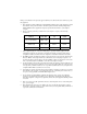
ISDN Information On a Motorola NT1D, you should see the following status lights when your ISDN lines are properly connected. Status SC ACT LB LP RP RPR ON ON OFF ON OFF OFF The dip switches should be set as follows: Switches 1 2 3 4 ON ON ON ON On an Alpha Telecom (AT1) UT620F, you should see the following status lights when your ISDN lines are properly connected.
ISDN Information ISDN Switches Depending on the type of ISDN lines you are using, your service provider may assign zero, one, or two SPIDs per line.
ISDN Information ISDN Errors (Continued) Code Cause 19 No answer from user (user alerted) The destination fails to complete the connection within the prescribed time after responding to the connection request. The problem occurs at the remote end of the connection. 21 Call rejected The destination rejects the call for an unknown reason, although capable of accepting the call. 22 Number changed No system has been assigned the ISDN number used to set up the call.
ISDN Information ISDN Errors (Continued) Code Cause Definition 57 Bearer capability not authorized The caller has requested a bearer capability that the network can provide, but the user is not authorized to use. This might be a subscription problem. 58 Bearer capability not presently available The network normally provides the requested bearer capability, but not at the present time. This might be due to a temporary network problem or to a subscription problem.
ISDN Information ISDN Errors (Continued) Code Cause Definition 95 Invalid message, unspecified An invalid message was received, and no standard cause applies. This is usually due to a D-channel error. If this error occurs systematically, report it to your ISDN service provider. 96 Mandatory information element is missing The receiving equipment received a message that did not include one of the mandatory information elements. This is usually due to a D-channel error.
Index A accessories document camera, 52 second monitor, 51 ShowStation IP, 52 VCR, 51 address book adding an entry, 37 creating multi-site entries, 111 deleting an entry, 42 editing an entry, 41 placing a call, 39 advanced network statistics for ViewStation 512 and MP, 117 audio, testing (for the ViewStation 512 and MP), 118 audio, testing, 88 automatic call answering, 36 automatic mode, 114 automatic voice tracking, 45 C cable connections, 16 cables connection diagram, 16 calls adding a telephone call in
Index D I data conferencing 77 setup information, 94 using a ShowStation IP, 77 using NetMeeting, 79 DHCP, 54 diagnostics advanced network statistics, 87 audio audio meter, 89, 119 generate tone, 88 call status, 87 color bar, 88 during a video call, 86 far end loop, 90 from the ViewStation, 85 from the web, 72 near end loop, 89 network statistics, 86 reset system, 90 ViewStation 512 and MP 117 advanced network statistics, 117 audio, 118 call status, 118 far end loop, 120 near end loop, 119 network statis
Index N name of your system, 19 network statistics for ViewStation 512 and MP, 117 NT-1 (definition), 14 NT-1, status indicator information, 129 P passwords for the web server, 71 on the Security screen, 96 PC, connecting to a ViewStation 53 no LAN connection, 55 on a LAN, 53 requirements, 53 PIP (definition), 30 power supply, 14 PowerPoint slides, 61 presentation mode, 115 presentations connecting a PC to the ViewStation, 53 showing slides, 63 viewing, 61 presets 44 automatic voice tracking to far-site c
Index SNMP status, 94 SoftUpdate application, 82 software (on the ViewStation) setup information, 97 software upgrades connecting a PC to the ViewStation, 53 enabling MP capabilities, 97, 122 over ISDN, 81 over the LAN, 82, 98 password location, 96 requirements, 82 sound, adjusting, 47 sound, testing, 88, 118 speed dialing, 103 on the ViewStation 512 and MP, 100 speed, changing, 27 speed-dial calls 29 locking a number, 30 speeds for multi-point calls, 110 speeds, in the address book, 42 SPID (definition),
Index W web server (in the ViewStation) 69 accessing, 69 changing the setup of a ViewStation, 74 controlling a system from the web, 73 Dial a Video Call web page, 75 General Setup web page, 74 Manage System web page, 71 placing calls from the web, 75 remote diagnostics, 72 sending messages to a ViewStation, 73 Welcome web page, 70 ViewStation User’s Guide 139
Index 140 ViewStation User’s Guide