
Installation Guide


9
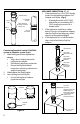
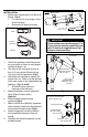
4. Slide cap through exterior wall plate into
hole from outside building
• Cap must be installed level or
sloped 1/8" per foot away from
appliance
5. Orient termination so air intake slots
face down
6. Seal termination to exterior wall plate
with silicone sealant
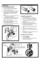
7. Slide interior wall plate over termination
and attach to wall from inside the room
8. Attach interior wall plate to termination
with provided hardware
9. Install gaskets into Co-Linear Adapter
10. Attach Co-Linear Adapter to Horizontal
Termination
11. Install Poly Pro venting system to/from
termination to appliance
Figure 13
SCREW TO
TERMINATION
AIR INTAKE
EXHAUST
COLINEAR
ADAPTER
INSTALL
GASKETS
EXTERIOR
WALL PLATE
INTERIOR
WALL PLATE
HORIZONTAL
TERMINATION
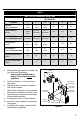
Table 3
Wall & Ceiling Penetration Sizing Table
VENT DIAMETER
Termination 2" 3" 4" 5" 6" 8"
CONCENTRIC
VERTICAL OR HORIZONTAL
4 ⁄"
105mm
5 ⁄"
130mm
6 ⁄"
155mm
N/A N/A N/A
TWIN PIPE HORIZONTAL
CLASS IIB
7 ⁄" x 2⁄"
187mm x
65mm
8 ⁄" x 3⁄"
212 x 85mm
9" x 4⁄"
228 x 100mm
N/A N/A N/A
TWIN PIPE HORIZONTAL
CLASS IIC (Framing Dimensions)
8" x 3"
200 x 77mm
8 ⁄" x 3⁄"
225 x 98mm
9 ⁄" x 4 ⁄"
238 x 112mm
N/A N/A N/A
SINGLE HORIZONTAL
CLASS IIB
2⁄"
65mm /
3 ⁄" "
85mm
4" "
100mm
N/A N/A N/A
SINGLE HORIZONTAL
CLASS IIC (Framing Dimensions)
3"
77mm
3 ⁄
98mm
4 ⁄
112mm
N/A N/A N/A
SINGLE WALL W/ LOCKING BAND
VERTICAL
3 ⁄" 4 ⁄" 5 ⁄" 6 ⁄" 7 ⁄" 9 ⁄"
SINGLE PIPE NO LOCKING BANDS
VERTICAL
3" 3 ⁄" 4 ⁄" 5 ⁄" 6 ⁄" 7 ⁄"