(Model 17-925) (Model 17-990X) MODEL 17-925 SHOWN PART NO. 909592 - 03-06-03 Copyright © 2003Delta Machinery To learn more about DELTA MACHINERY visit our website at: www.deltamachinery.com. For Parts, Service, Warranty or other Assistance, please call 1-800-223-7278 (In Canada call 1-800-463-3582).
SAFETY GUIDELINES - DEFINITIONS This manual contains information that is important for you to know and understand. This information relates to protecting YOUR SAFETY and PREVENTING EQUIPMENT PROBLEMS. To help you recognize this information, we use the symbols to the right. Please read the manual and pay attention to these sections. Indicates an imminently hazardous situation which, if not avoided, will result in death or serious injury.
16. USE RECOMMENDED ACCESSORIES. The use of accessories and attachments not recommended by Delta may cause hazards or risk of injury to persons. 17. REDUCE THE RISK OF UNINTENTIONAL STARTING. Make sure switch is in “OFF” position before plugging in power cord. In the event of a power failure, move switch to the “OFF” position. 18. NEVER STAND ON TOOL. Serious injury could occur if the tool is tipped or if the cutting tool is accidentally contacted. 19. CHECK DAMAGED PARTS.
POWER CONNECTIONS A separate electrical circuit should be used for your machines. This circuit should not be less than #12 wire and should be protected with a 20 Amp time lag fuse. If an extension cord is used, use only 3-wire extension cords which have 3prong grounding type plugs and matching receptacle which will accept the machine’s plug.
When converted for 230 volt operation, your drill press is intended for use on a circuit that has an outlet like the one illustrated in Fig. C. After conversion for 230 volts, the drill press will have a grounding plug that looks like the plug illustrated in Fig. C. Make sure the drill press is connected to an outlet having the same configuration as the plug. No adapter is available or should be used when the drill press is converted for 230 volts.
DRILL PRESS PARTS 15 1 16 17 2 18 3 6 8 7 5 4 14 10 9 13 11A 11B 12 Fig. 2 12345678910 11A 11B 12 13 14 15 - Speed range changing lever Speed changing levers (2) Base M8 x 125mm carriage head screw (2), M8 Flat washer (2), M8.
ASSEMBLY FOR YOUR OWN SAFETY, DO NOT CONNECT THE MACHINE TO THE POWER SOURCE UNTIL THE MACHINE IS COMPLETELY ASSEMBLED AND YOU READ AND UNDERSTAND THE ENTIRE INSTRUCTION MANUAL. 1. Assemble the column (A) Fig. 3, to the base (B) using the four M10x40mm hex head screws (C), three of which are shown. Loosen set screw (D) with 3mm wrench supplied, and remove ring (E) and raising rack (F). E D F A B 2. Insert small end of worm gear (G) Fig. 4 and Fig.
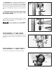
F I Fig. 7 4. Slide raising rack (F) Fig. 7 and table bracket (I) onto drill press column, as shown. Make sure bottom of raising rack (F) Fig. 8, is engaged with flange (J) on drill press base. F J Fig. 8 5. Re-assemble ring (E) Fig. 9, which was removed in STEP 1. IMPORTANT: Bottom of ring (E) MUST NOT be pushed all the way down onto top of raising rack (F). MAKE SURE top of raising rack (F) is under bottom of ring (E) and that there is enough clearance to allow rack (F) to rotate around the column.
7. Thread clamp handle (M) Fig. 11, into hole in rear of table bracket, as shown. M Fig. 11 8. Insert table (P) Fig. 12, into hole in table bracket as shown. P Fig. 12 9. Thread table lock lever (Q) Fig. 13, into hole in front of table bracket as shown. 10. Place the drill press head (N) Fig. 14, onto the column as far as it will go. Align head (N) Fig. 14A, to table (C) Fig. 14A, and base (D) Fig. 14A, and tighten the two head locking screws (O) Fig. 14 with the 5mm wrench supplied. Q Fig.
11. IMPORTANT: Make certain the spindle taper (Q) Fig. 15, and tapered hole in chuck (R) are clean and free of any grease, lacquer or rust preventive coatings. NOTE: Household oven cleaner can effectively remove any substance from the spindle and chuck; however, carefully follow the manufacturer's safety rules concerning its use. Q R 12. IMPORTANT: OPEN THE CHUCK JAWS AS WIDE AS POSSIBLE MAKING SURE THE CHUCK JAWS ARE UP INSIDE CHUCK. Fig. 15 13.
Place handle (A) Fig. 17B on pinion shaft (C). Make sure key slot (D) in handle is aligned with the key (E) on the pinion shaft A D C E Fig. 17B Replace flat washer (C) Fig. 17C and thread screw (B) into pinion shaft and tighten securely. C B Fig. 17C 15. Thread the two speed changing levers (W) Fig. 18, into the speed changing hub as shown. W W Fig. 18 16. Thread the speed range changing lever (X) Fig. 19, into hub as shown. X Fig.
FASTENING DRILL PRESS BASE TO A SUPPORTING SURFACE PERMANENT MOUNTING If your drill press is to be used in a permanent location, the drill press base must be secured to the supporting surface with fasteners through the two mounting holes, (A) Fig. 20, in the drill press base. A Fig.
OPERATING CONTROLS AND ADJUSTMENTS STARTING AND STOPPING DRILL PRESS A The power switch is located at the front of the drill press head. To turn the machine “ON” press the green start button (A) Fig. 23. To stop the drill press, push the red stop button (B). B Fig. 23 LOCKING SWITCH IN THE “OFF” POSITION C IMPORTANT: When the machine is not in use, the switch should be locked in the OFF position using a padlock (C) Fig. 24, with a 3/16" diameter shackle to prevent unauthorized use.
VARIABLE SPEED CONTROL B DO NOT turn variable speed pilot wheel handles (A) Fig. 28, unless motor is running to avoid putting unnecessary strain on the drive belts and pulleys. The pilot wheel handles (A) are turned clockwise to increase speed and counterclockwise to decrease speed. When changing speeds, the pointer (B) will indicate the speed of the drill press. A A Fig. 28 SPEED RANGE CONTROL A The speed range control lever (A) Fig. 29, MUST NOT be moved except when the motor is running.
QUILL ADJUSTMENTS D The spindle is raised and lowered by turning the pilot wheel (A) Fig. 31. The quill (B) can be locked at any desired point in its travel by tightening the quill locking lever (C). NOTE: The quill locking lever (C) is springloaded and the handle can be repositioned by pulling out on the handle (C) and repositioning the hub (D) of the handle on the nut located underneath the hub. C A E B The adjusting screw (E) Fig. 31, and nut (F) Fig.
OPERATIONS Your drill press is to be used with drill bits with a shank of 1/2" or less in diameter. The following will give the inexperienced operator a start on common drill press operations. Use scrap material for practice to get a feel of the machine before attempting regular work. The use of accessories and attachments not recommended by Delta may result in risk of injury.
BORING IN WOOD Twist drills, although intended for metal drilling, may also be used for boring holes in wood. However, machine spur bits are generally preferred for working in wood; they cut a flat bottom hole and are designed for removal of wood chips. Do not use hand bits which have a screw tip; at drill press speeds they turn into the wood so rapidly as to lift the work off the table and whirl it.
MAINTENANCE LUBRICATION B A A Fig. 36 The variable speed pulleys and the speed range shifter mechanism should be oiled weekly with a few drops of light machine oil in the two oil holes (A) Fig. 38, located on top of the variable speed pulleys and the hole (B) located on top of the shifter mechanism. IMPORTANT: Oil the holes when the drill press is turned OFF. Then turn the machine ON and run through the low and high speed ranges a few times.
ACCESSORIES A complete line of accessories is available from your Delta Supplier, Porter-Cable • Delta Factory Service Centers, and Delta Authorized Service Stations. Please visit our Web Site www.deltamachinery.com for a catalog or for the name of your nearest supplier. Since accessories other than those offered by Delta have not been tested with this product, use of such accessories could be hazardous. For safest operation, only Delta recommended accessories should be used with this product.
PORTER-CABLE • DELTA SERVICE CENTERS (CENTROS DE SERVICIO DE PORTER-CABLE • DELTA) Parts and Repair Service for Porter-Cable • Delta Machinery are Available at These Locations (Obtenga Refaccion de Partes o Servicio para su Herramienta en los Siguientes Centros de Porter-Cable • Delta) ARIZONA Tempe 85282 (Phoenix) 2400 West Southern Avenue Suite 105 Phone: (602) 437-1200 Fax: (602) 437-2200 CALIFORNIA Ontario 91761 (Los Angeles) 3949A East Guasti Road Phone: (909) 390-5555 Fax: (909) 390-5554 San Leandro