(Model 28-248) (Model 28-475X) PART NO. 426-02-651-0055 - 06-10-03 Copyright © 2003 Delta Machinery To learn more about DELTA MACHINERY visit our website at: www.deltamachinery.com. For Parts, Service, Warranty or other Assistance, please call 1-800-223-7278 (In Canada call 1-800-463-3582).
SAFETY GUIDELINES - DEFINITIONS This manual contains information that is important for you to know and understand. This information relates to protecting YOUR SAFETY and PREVENTING EQUIPMENT PROBLEMS. To help you recognize this information, we use the symbols to the right. Please read the manual and pay attention to these sections. Indicates an imminently hazardous situation which, if not avoided, will result in death or serious injury.
FAILURE TO FOLLOW THESE RULES MAY RESULT IN SERIOUS PERSONAL INJURY. 1. 2. 3. 4. 5. 6. 7. 8. 9. 10. 11. 12. FOR YOUR OWN SAFETY, READ THE INSTRUCTTION MANUAL BEFORE OPERATING THE MACHINE. Learning the machine’s application, limitations, and specific hazards will greatly minimize the possibility of accidents and injury. USE CERTIFIED SAFETY EQUIPMENT. Eye protection equipment should comply with ANSI Z87.1 standards, hearing equipment should comply with ANSI S3.
ADDITIONAL SAFETY RULES FOR BAND SAWS FAILURE TO FOLLOW THESE RULES MAY RESULT IN SERIOUS PERSONAL INJURY. 1. DO NOT OPERATE THIS MACHINE UNTIL it is assembled and installed according to the instructions. 15. TURN THE MACHINE “OFF” to back out of an uncompleted or jammed cut. 2. OBTAIN ADVICE from your supervisor, instructor, or another qualified person if you are not familiar with the operation of this tool. 17.
POWER CONNECTIONS A separate electrical circuit should be used for your machines. This circuit should not be less than #12 wire and should be protected with a 20 Amp time lag fuse. If an extension cord is used, use only 3-wire extension cords which have 3prong grounding type plugs and matching receptacle which will accept the machine’s plug.
3. Grounded, cord-connected machines intended for use on a supply circuit having a nominal rating between 150 - 250 volts, inclusive: If the machine is intended for use on a circuit that has an outlet that looks like the one illustrated in Fig. C, the machine will have a grounding plug that looks like the plug illustrated in Fig. C. Make sure the machine is connected to an outlet having the same configuration as the plug. No adapter is available or should be used with this machine.
UNPACKING AND CLEANING Carefully unpack the machine and all loose items from the shipping container(s). Remove the protective coating from all unpainted surfaces. This coating may be removed with a soft cloth moistened with kerosene (do not use acetone, gasoline or lacquer thinner for this purpose). After cleaning, cover the unpainted surfaces with a good quality household floor paste wax. 1. Remove the cardboard box from around the packing skid (A) Fig. 2. 2. Remove the two bolts (B) Fig.
BAND SAW PARTS 6 7 A 8 2 1 9 11 12 10 14 13 15 3 16 4 17 18 5 19 20 21 22 23 Fig. 4 24 25 26 27 28 Fig. 5 1. Saw 15. 5/16-18x1½" Hex Head Screw (4) 2. Stand 16. 5/16-18x3/4" Carriage Head Bolt (16) 3. Dust Chute 17. #10-24x1/2" Socket Head Cap Screw (8) 4. Top Plate 18. #10-32x1/2" Pan Head Screw (4) 5. Stand Door 19. 5/16" Flat Washer (4) 6. Motor and key (A) 20. 7/16" Jam Nut (2) 7. Table 21. 7/16" Locknut (2) 8. Belt 22. 5/16-18 Hex Nut (20) 9. On/Off Switch 23.
ASSEMBLY FOR YOUR OWN SAFETY, DO NOT CONNECT THE MACHINE TO THE POWER SOURCE UNTIL THE MACHINE IS COMPLETELY ASSEMBLED AND YOU READ AND UNDERSTAND THE ENTIRE INSTRUCTION MANUAL. MOTOR BRACKET TO STAND 1. Place the stand base on its side as shown in Fig. 6. E 2. Align the two holes in the motor bracket (A) Fig. 7, with the two holes in the stand. NOTE: ATTACH MOTOR BRACKETS TO HOLES #1 AND 3 IN FRONT STAND FLANGE (D) FIG. 6, AND HOLES #2 AND 4 IN BACK STAND FLANGE (E).
TOP PLATE TO STAND 1. Place the top plate (A) Fig. 10, on the top of the stand (B). A 2. Align the six square holes on the top plate (A) Fig. 10, with the six square holes in the stand (B). 3. Align the two square holes on the side of the plate (A) Fig. 10, with the two square holes on the side of the stand (B). B 4. Insert a 5/16-18x3/4" carriage head bolt through the top plate and the stand. Thread a 5/16-18 hex nut on to screw. Fig. 10 A 5.
BAND SAW USED WITH A DUST COLLECTOR B B 3. If you are going to use your band saw with a dust collector, attach the dust port as follows: A A. Align the four holes in the dust port (A) Fig. 15, with the four holes in the side of the stand. B. Insert a #10-32x1/2" pan head screw through the two holes in the dust port (B) Fig. 15, and stand. Thread a #10-32 hex nut onto the screw, and tighten securely. C C Fig. 15 C.
6. Align the two holes in the hinge (C) Fig. 19, with the two holes in the stand door (D). MAKE SURE THAT THE HINGE OPENING IS POINTING DOWN. C 7. Insert a #10-24x1/2" socket head cap screw through the hole in the door, and thread the screw into the hole in the hinge. Repeat this process for the remaining hole in the door and the hinge. NOTE: DO NOT COMPLETELY TIGHTEN THE SCREWS AT THIS TIME. D 8. Repeat this process for the remaining hinge. Fig. 19 9.
SAW TO STAND A THE BAND SAW IS VERY HEAVY. USE A HELPER WHEN ATTACHING THE SAW TO THE STAND. 1. Place the band saw on top of the stand as shown in Fig. 23. NOTE: MAKE SURE THE PULLEY (A) FIG. 23, IS ON THE SIDE OF THE STAND WITH THE BELT OPENING (B). B C 2. Align the four holes in the saw with the four holes in the top of the stand. Fig. 23 3. Place a 5/16" flat washer onto a 5/16-18x1½" hex head screw. Insert the screw through the hole (C) in the saw and the stand. 4.
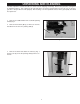
TABLE TO SAW C 1. Align the two table studs (A) Fig. 27, in the bottom of the table, with the two holes in the trunnion assemblies (B). Place table on trunnion assemblies. NOTE: MAKE SURE THE SLOT (C) FIG. 27, IN THE TABLE IS FACING AWAY FROM THE ARM (D). A D A B B 2. Thread a 7/16" jam nut (C) Fig. 28 onto each table stud and tighten securely. Fig. 27 C C Fig. 28 3. Place the table handle (H) on each stud as shown in Fig. 29. NOTE: MAKE SURE THE TABLE HANDLES ARE POSITIONED AS SHOWN IN FIG.
BLADE TO SAW B D THE 14" BAND SAW USES 93½" LENGTH BLADES. E 1. Remove the table pin (A) Fig. 31 from the table. 2. Open the two wheel guard doors (B) Fig. 31, and the blade guard door (C). A B 3. Make sure the quick tension lever (D) Fig. 31, is positioned to the right of the machine, to relieve tension as shown. C Fig. 31 4. NOTE: CHECK BLADE TO BE SURE TEETH WILL POINT DOWN TOWARD TABLE WHEN INSTALLED. IF NOT, TURN BLADE INSIDE OUT.
ON / OFF SWITCH TO STAND B A 1. Remove the two outer hex nuts and lock washers (A) Fig. 34 from the two screws extending out from the back of the switch box (B). A Fig. 34 2. Insert two screws (C) Fig. 35, located on back of switch box, into two holes (D) located in the band saw arm. D C Fig. 35 3. Use the two nuts and lockwashers (L) Fig. 36, removed in STEP 1, to fasten the switch box to the bandsaw arm. 4. Remove the screw and cable clamp (E) Fig. 37 from the lower arm of the band saw. L 5.
7. Insert the switch cord (H) Fig. 39, through the hole in the cord bushing (G). H G Fig. 39 8. Insert the pronged motor plug (J) Fig. 40, into the receptacle (H) of switch cord. MAKE SURE THAT THE MOTOR PLUG (J) FIG. 40 AND THE SWITCH CORD (H) ARE ROUTED BEHIND THE DUST CHUTE (K). IF THE BAND SAW IS BEING USED WITH THE ACCESSORY HEIGHT ATTACHMENT THE THE CORD HAS TO BE ROUTED IN FRONT OF THE DUST CHUTE. J H K Fig.
TILTING THE TABLE DISCONNECT MACHINE FROM POWER SOURCE. D 1. The table on the band saw can be tilted 45 degrees to the right and 8 degrees to the left. To tilt the table to the right, loosen the two clamp handles (A) Fig. 43, tilt the table to the desired angle as shown on the scale (D) Figs. 43 and 44, and tighten two locking handles (A) Fig. 43. A A Fig. 43 2. To tilt the table to the left, loosen the two locking handles (A) Fig. 43, and tilt the table to the right until the table stops (B) Fig.
To set the adjustable stops: DISCONNECT MACHINE FROM POWER SOURCE. 1. Loosen the two clamp handles (A) Fig. 43. J 2. Tilt the table to the right, and turn the stop until either stop screw (M) or (N) Fig. 48, is under the table skirt. K 3. Tilt the table to the left until it rests on the selected stop screw (M) or (N) Fig. 48. Fig. 47 4. The angle can be set by turning the stop screw and checking the angle on the side of the scale with pointer (J) Fig. 47. 5.
5. The band saw blade tension can be fined tune by turning adjustment nut (N) Fig. 51, while the blade is tensioned. B 6. A series of graduations is located on the back of the upper wheel slide bracket (T) Fig. 51. These graduations indicate the proper tension for various widths of blades. C T NOTE: THESE GRADUATIONS ARE CORRECT FOR AVERAGE WORK, AND WILL NOT BE AFFECTED BY REBRAZING OF THE SAW BLADE.
ADJUSTING THE UPPER BLADE GUIDES AND BLADE SUPPORT BEARING Adjust the upper blade guides and blade support bearings ONLY AFTER the blade has the correct tension and is tracking properly. To adjust, do the following: DISCONNECT MACHINE FROM POWER SOURCE B C 1. Make sure that the bottom blade guides and support bearings are not touching the blade. A 2. Check the upper blade guide assembly. The blade guides (A) Fig. 54 should be parallel to the blade.
ADJUSTING LOWER BLADE GUIDES AND BLADE SUPPORT BEARING B E A A B Adjust the lower blade guides and blade support bearing after the upper guides and bearing have been adjusted. C DISCONNECT MACHINE FROM POWER SOURCE. D 1. Adjust the front edge of the guide blocks (B) Fig. 56 so that they are just behind the “gullets” of the saw teeth. Turn the knurled knob (C) Fig. 56 to make this adjustment. Check the support bearing (D) Fig. 56. It should not be touching the back of the blade. Fig. 56 2.
TROUBLESHOOTING GUIDE In spite of how well a band saw is maintained, problems can occur. The following troubleshooting guide will help you solve the more common problems: Trouble: SAW WILL NOT START. Probable Cause Remedy 1. Switch cord / motor cord not plugged in. 1. Plug in switch cord / motor cord. 2. Fuse blown or motor reset tripped. 2. Replace fuse or push motor reset button. 3. Cord damaged. 3. Have cord replaced. Trouble: BREAKER OR MOTOR KICKS OUT FREQUENTLY. Probable Cause Remedy 1.
Trouble: BLADE WILL NOT TRACK. Probable Cause Remedy 1. Blade too loose 1. Adjust tension 2. Upper wheel not properly adjusted. 2. Adjust upper wheel. 3. Improperly adjusted blade support bearing. 3. Adjust blade support bearing. Trouble: CUT DOES NOT AGREE WITH SETTING ON THE TILT SCALE. Probable Cause Remedy 1. Pointer out of adjustment 1. Adjust pointer. Trouble: BLADE WILL NOT STAY ON WHEEL. Probable Cause Remedy 1. Blade not tensioned properly. 1. Adjust blade tension. 2.
BAND SAW BLADES A band saw blade is a delicate piece of steel that is subjected to tremendous strain. You can obtain long use from a band saw blade if you use it properly. Be sure you use blades of the proper thickness, width and temper for the various types of material and cuts. Always use the widest blade possible. Use narrow blades only for sawing small, abrupt curves and for fine, delicate work. This will save blades and will produce better cuts.
NOTES 26
ACCESSORIES A complete line of accessories is available from your Delta Supplier, Porter-Cable • Delta Factory Service Centers, and Delta Authorized Service Stations. Please visit our Web Site www.deltamachinery.com for a catalog or for the name of your nearest supplier. Since accessories other than those offered by Delta have not been tested with this product, use of such accessories could be hazardous. For safest operation, only Delta recommended accessories should be used with this product.
PORTER-CABLE • DELTA SERVICE CENTERS (CENTROS DE SERVICIO DE PORTER-CABLE • DELTA) Parts and Repair Service for Porter-Cable • Delta Machinery are Available at These Locations (Obtenga Refaccion de Partes o Servicio para su Herramienta en los Siguientes Centros de Porter-Cable • Delta) ARIZONA Tempe 85282 (Phoenix) 2400 West Southern Avenue Suite 105 Phone: (602) 437-1200 Fax: (602) 437-2200 CALIFORNIA Ontario 91761 (Los Angeles) 3949A East Guasti Road Phone: (909) 390-5555 Fax: (909) 390-5554 San Leandro