
Product Manual


14
14
POSITIONING GROOVES
The number of grooves (biscuits) used in a joint may be varied to provide the strength
required for the particular application. Typically position the center of the first groove
approximately 2" (50.8mm) from the edge of the work with additional grooves spaced
at 3" to 6" (76.2mm to 152.4mm) on centers.
M
I
T
E
R
J
O
I
N
T
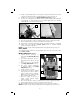
CORNER
JOINT
FIG. 27A
SURFACE
JOINT
FIG. 27B FIG. 27C
In most cases use one line of grooves
BUTT
JOINT
FIG. 27D
(biscuits) positioned approximately along
the centerline of the material. On thicker
material use an additional row(s) of biscuits
for added strength.
Position the two workpieces (to be joined)
in the relationship desired after joining.
Mark the centerline of each groove
required as shown in Fig.
27A–D. Use a
square to assure accuracy.
PRACTICE CUTS
After each set-up or adjustment to the
tool make several practice cuts in scrap material.
CORNER JOINTS
1. Layout groove positions as described in Positioning Grooves section.
2. Set depth stop turret to desired biscuit (or other accessory) size.
3. Set the tilt fence to the 90° position (see Angle Adjustment section).
4. Set fence height adjustment to desired height (usually half the material thickness),
(see Height Adjustment section.)
5. Clamp the workpiece securely.