ESPAÑOL: PÁGINA 21 FRANÇAIS : PAGE 41 Pancake Compressor Instruction manual MODEL CFFN251T To learn more about Porter-Cable visit our website at: IMPORTANT Please make certain that the person who is to use this equipment carefully reads and understands these instructions before starting operations. http://www.porter-cable.com The Model and Serial No. plate is located on the main housing of the tool. Record these numbers in the spaces below and retain for future reference.
TABLE OF CONTENTS SAFETY GUIDELINES . . . . . . . . . . . . . . . . . . . . . . . . . . . . . . . . . . . . . . . 2-7 SPECIFICATIONS . . . . . . . . . . . . . . . . . . . . . . . . . . . . . . . . . . . . . . . . . . . .8 GLOSSARY . . . . . . . . . . . . . . . . . . . . . . . . . . . . . . . . . . . . . . . . . . . . . . . . .8 DUTY CYCLE . . . . . . . . . . . . . . . . . . . . . . . . . . . . . . . . . . . . . . . . . . . . . . .8 ACCESSORIES . . . . . . . . . . . . . . . . . . . . . . . . . . . . . . . .
IMPORTANT SAFETY INSTRUCTIONS Save these instructions Improper operation or maintenance of this product could result in serious injury and property damage. Read and understand all warnings and operation instructions before using this equipment. HAZARD WARNING: Risk of explosion or fire What Could Happen How To Prevent It It is normal for electrical contacts within the motor and pressure switch to spark.
HAZARD WARNING: Risk of Bursting Air Tank: The following conditions could lead to a weakening of the tank, and result in a violent tank explosion and could cause property damage or serious injury. How To Prevent It What Could Happen Failure to properly drain condensed water from tank, causing rust and thinning of the steel tank. Drain tank daily or after each use. If tank develops a leak, replace it immediately with a new tank or replace the entire compressor.
HAZARD WARNING: Risk of Electrical Shock What Could Happen How To Prevent It Your air compressor is powered by electricity. Like any other electrically powered device, If it is not used properly it may cause electric shock. Never operate the compressor outdoors when it is raining or in wet conditions. Never operate compressor with protective covers removed or damaged. Repairs attempted by unqualified personnel can result in serious injury or death by electrocution.
HAZARD WARNING: Risk of Burns What Could Happen How To Prevent It Never touch any exposed metal parts on compressor during or immediately after operation. Compressor will remain hot for several minutes after operation. Do not reach around protective shrouds or attempt maintenance until unit has been allowed to cool. Touching exposed metal such as the compressor head or outlet tubes, can result in serious burns.
HAZARD WARNING: Risk of Serious Injury or Property Damage When Transporting Compressor (Fire, Inhalation, Damage to Vehicle Surfaces) What Could Happen How To Prevent It Oil can leak or spill and could result in fire or breathing hazard; serious injury or death can result. oil leaks will damage carpet, paint or other surfaces in vehicles or trailers. Always place COMPRESSOR on a protective mat when transporting to protect against damage to vehicle from leaks.
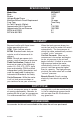
SPECIFICATIONS Model Nos. Bore Stroke Voltage-Single Phase Minimum Branch Circuit Requirement Fuse Type Air Tank Capacity (Gallon) Approximate Cut-in Pressure Approximate Cut-out Pressure SCFM @ 40 PSIG SCFM @ 90 PSIG CFFN251T 1.875" 1.250" 120 15 amps Time Delay 6 110 PSIG 135 PSIG 3.7 2.6 GLOSSARY Become familiar with these terms before operating the unit. CFM: Cubic feet per minute. SCFM: Standard cubic feet per minute; a unit of measure of air delivery.
ASSEMBLY Unpacking 1. Remove unit from carton and discard all packaging. INSTALLATION HOW TO SET UP YOUR UNIT Location of the Air Compressor • • • Locate the air compressor in a clean, dry and well ventilated area. The air compressor should be located at least 12" away from the wall or other obstructions that will interfere with the flow of air. The air compressor pump and shroud are designed to allow for proper cooling.
Extension Cords Voltage and Circuit Protection Using extension cords is not recommended. The use of extension cords will cause voltage to drop resulting in power loss to the motor and overheating. Instead of using an extension cord, increase the working reach of the air hose by attaching another length of hose to its end. Attach additional lengths of hose as needed. If an extension cord must be used, be sure it is: Refer to the specification chart for the voltage and minimum branch circuit requirements.
OPERATION Know Your Air Compressor READ THIS OWNER’S MANUAL AND SAFETY RULES BEFORE OPERATING YOUR UNIT. Compare the illustrations with your unit to familiarize yourself with the location of various controls and adjustments. Save this manual for future reference. On(I)/Off(O) Switch Tank Pressure Gauge Outlet Pressure Gauge Quick Connect Safety Valve Regulator Description of Operation Become familiar with these controls before operating the unit.
Drain Valve: The drain valve is located at the base of the Drain Valve air tank and is used to drain condensation at the end of each use. Check Valve: When the air compressor is operating, the check valve is "open", allowing compressed air to enter the air tank. When the air compressor reaches "cut-out" pressure, the check valve "closes", allowing air pressure to remain inside the air tank. Check Valve 2. Plug the power cord into the correct branch circuit receptacle.
Risk of Bursting. Too much air pressure causes a hazardous risk of bursting. Check the manufacturer’s maximum pressure rating for air tools and accessories. The regulator outlet pressure must never exceed the maximum pressure rating. How to Start: 1. Set the On/Off switch to ON (I) and allow tank pressure to build. Motor will stop when tank pressure reaches "cut-out" pressure. 2. Pull the regulator knob out and turn clockwise to increase pressure.
To Drain Tank 1. Set the On/Off switch to OFF (O). 2. Pull the regulator knob out and turn counterclockwise to set the outlet pressure to zero. 3. Remove the air tool or accessory. 4. Pull ring on safety valve allowing air to bleed from the tank until tank pressure is approximately 20 psi. Release safety valve ring. 5. Drain water from air tank by opening drain valve on bottom of tank. Water will condense in the air tank.
5. Make sure the valve disc moves freely inside the check valve and the spring holds the disc in the upper, closed position. The check valve may be cleaned with a solvent, such as paint and varnish remover. 6. Apply sealant to the check valve threads. Reinstall the check valve (turn clockwise). 7. Replace hose and new hose clamp. 8. Perform the Break-in Procedure. See "Break-in Procedure" in the Operation section. 5. Remove pump mounting screws securing pump (one on each side). 6.
STORAGE Risk of Bursting. Water will condense in the air tank. If not drained, water will corrode and weaken the air tank causing a risk of air tank rupture. Before you store the air compressor, make sure you do the following: 1. Review the "Maintenance" section on the preceding pages and perform scheduled maintenance as necessary. 2. Set the On/Off switch to OFF (O) and unplug unit. 3. Turn the regulator counterclockwise and set the outlet pressure to zero. 4. Remove the air tool or accessory. 5.
TROUBLESHOOTING Performing repairs may expose voltage sources, moving parts or compressed air sources. Personal injury may occur. Prior to attempting any repairs, unplug the air compressor and bleed off all air tank air pressure. PROBLEM CAUSE Pressure switch does Excessive tank pressure - safety not shut off motor when compressor reaches "cutvalve pops off. out" pressure. CORRECTION Set the On/Off switch to OFF (O), if the unit does not shut off contact a Trained Service Technician.
PROBLEM CAUSE Pressure reading It is normal for "some" on the regulated pressure drop to occur. pressure gauge drops when an accessory is used. CORRECTION If there is an excessive amount of pressure drop when the accessory is used, adjust the regulator following the instructions in the "Description of Operation" paragraph in the "Operation Section. NOTE: Adjust the regulated pressure under flow conditions (while accessory is being used). Prolonged excessive use of air. Decrease amount of air usage.
SERVICE REPLACEMENT PARTS When servicing use only identical replacement parts. For a service parts list or to learn more about Porter-Cable visit our website at www.porter-cable.com. SERVICE AND REPAIRS All quality tools will eventually require servicing, or replacement of parts due to wear from normal use. For assistance with your tool, visit our website at www.porter-cable.com for a list of service centers or call the Customer Care Department at 1-800-487-8665.
WARRANTY Warranty Registration To register your tool for warranty service visit our website at www.porter-cable.com. Limited Warranty Porter-Cable warrants to the original purchaser that all products covered under this warranty are free from defects in material and workmanship.