ESPAÑOL: PÁGINA 23 FRANÇAISE : PAGE 43 Instruction Manual Double Insulated 10" Bench Top Table Saw MODEL 3812 Shown assembled with accessory stand model 38129 and accessory outfeed support model 38239. To learn more about Porter-Cable visit our website at: http://www.porter-cable.com IMPORTANT Please make certain that the person who is to use this equipment carefully reads and understands these instructions before starting operations. The Model and Serial No.
SAFETY GUIDELINES - DEFINITIONS This manual contains information that is important for you to know and understand. This information relates to protecting YOUR SAFETY and PREVENTING EQUIPMENT PROBLEMS. To help you recognize this information, we use the symbols to the right. Please read the manual and pay attention to these sections. Indicates an imminently hazardous situation which, if not avoided, will result in death or serious injury.
FAILURE TO FOLLOW THESE RULES MAY RESULT IN SERIOUS INJURY. 1. 2. 3. 4. 5. 6. 7. 8. 9. 10. 11. 12. 13. FOR YOUR OWN SAFETY, READ THE INSTRUCTION MANUAL BEFORE OPERATING THE MACHINE. Learning the machine’s application, limitations, and specific hazards will greatly minimize the possibility of accidents and injury. USE CERTIFIED SAFETY EQUIPMENT. Eye protection equipment should comply with ANSI Z87.1 standards, hearing equipment should comply with ANSI S3.
ADDITIONAL SAFETY RULES FOR TABLE SAWS FAILURE TO FOLLOW THESE RULES MAY RESULT IN SERIOUS INJURY. 1. DO NOT OPERATE THIS MACHINE until it is assembled and installed according to the instructions. 10. NEVER perform “free-hand” operations. Use either the fence or miter gauge to position and guide the workpiece. 2. OBTAIN ADVICE FROM YOUR SUPERVISOR, instructor, or another qualified person if you are not familiar with the operation of this machine. 11.
POWER CONNECTIONS A separate electrical circuit should be used for your machines. This circuit should not be less than #12 wire and should be protected with a 20 Amp time lag fuse. If an extension cord is used, use only 3-wire extension cords which have 3prong grounding type plugs and matching receptacle which will accept the machine’s plug.
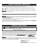
CARTON CONTENTS 1 2 4 3 5 6 Fig. 2 1. Saw 2. Fence 3. Table Insert 4. Blade Guard and Spreader Assembly 5. Blade Wrench (2) 6. Miter Gauge 7. Anchor Block Shim (3) 8. Handle 9.
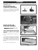
ASSEMBLY FOR YOUR OWN SAFETY, DO NOT CONNECT THE MACHINE TO THE POWER SOURCE UNTIL THE MACHINE IS COMPLETELY ASSEMBLED AND YOU READ AND UNDERSTAND THE ENTIRE INSTRUCTION MANUAL. BLADE RAISING AND LOWERING HANDWHEEL E D Insert the 1-3/4" screw (D) Fig. 4, through handle (E). Assemble handle (E) to handwheel (A) by threading screw (D) clockwise into handwheel as shown in Fig. 5. Handle (E) should rotate freely on screw (D). Fig. 4 E D A Fig. 5 BLADE GUARD AND SPREADER ASSEMBLY 1.
6. NOTE: The anchor block (B) Fig. 6, has been adjusted at the factory so that the spreader will be aligned with the saw blade which is supplied with the saw. When changing to blades with different widths it may be necessary to adjust the anchor block (B) Fig. 9, as follows: 7. Remove table insert and saw blade. 8. Loosen the two screws (C) Fig. 8 (under saw table), that attach the anchor block (B) Fig. 9, to the saw frame (E). 9. Three additional shims, two of which are shown at (D) Fig.
RIP FENCE TO SAW TABLE 1. The rip fence may be used on the right or left hand side of the saw table. Lift locking handle (A) Fig. 12, and position the front end of the fence on the front fence rail as shown. A 2. While pressing front end of fence firmly against front fence rail, place rear end of fence down on the rear fence rail and push down on locking handle (A) Fig. 13, to lock fence in place. Fig.
OPERATING CONTROLS AND ADJUSTMENTS STARTING AND STOPPING SAW The “ON/OFF” switch (A) Fig 16, is located on the front of the saw cabinet. To turn the saw “ON” pull the “ON/OFF” switch (A) out. To turn the saw “OFF”, push in on the “ON/OFF” switch (A). SOFT START A Model 3812 has a “Soft Start” feature designed to minimize startup reaction torque. LOCKING SWITCH IN THE “OFF” POSITION Fig.
ADJUSTING 0 AND 45 DEGREE POSITIVE STOPS A Your saw is equipped with positive stops for rapid and accurate positioning of the saw blade at 0 and 45 degrees to the table. This saw has the capability to go 2 degrees beyond 0 and 45 degrees (-2º to 47º). To adjust the positive stops, proceed as follows: 1. DISCONNECT MACHINE FROM POWER SOURCE. 2. Remove the blade guard and spreader assembly. NOTE: SEE THE SECTION “REMOVING BLADE GUARD/SPREADER ASSEMBLY.” 3. Raise the saw blade to its maximum height. B Fig.
3. THE RIP FENCE MUST BE PARALLEL TO THE MITER GAGE SLOT AND SAW BLADE TO HELP PREVENT KICKBACK WHEN RIPPING. 4. The saw blade is set parallel to the miter gage slot at the factory and the fence must be parallel to the miter gage slot and saw blade in order to do accurate work and help prevent kickback when ripping. To check the alignment: 5. Position the fence close to the miter gage slot, as shown in Fig. 22A. Push fence toward saw to insure alignment screws are in contact with the fence rail.
MITER GAGE OPERATION AND ADJUSTMENTS When straight cross-cutting (blade set 90 degrees to the table) the miter gage can be used in either table slot. When bevel cross-cutting (blade tilted) only use the miter gage in the right table slot where the blade is tilted away from the miter gage and your hands. This miter gage is equipped with individually adjustable index stops at 90 degrees and 45 degrees right and left. Adjustment to the index stops can be made by loosening lock nuts (B) Fig.
OPERATIONS Common sawing operations include ripping and cross-cutting plus a few other standard operations of a fundamental nature. As with all power tools, there is a certain amount of hazard involved with the operation and use of the tool. Using the tool with the respect and caution demanded as far as safety precautions are concerned, will considerably lessen the possibility of personal injury. However, if normal safety precautions are overlooked or ignored, personal injury to the operator can result.
If the ripped work is less than 4 inches wide, a PUSH STICK should always be used to complete the feed, as shown in Fig. 35. The PUSH STICK can easily be made from scrap material as explained in the section “CONSTRUCTING PUSH STICK.” When ripping stock 2 inches or narrower, assemble an auxiliary wood facing to the fence, as explained in the section “USING AUXILIARY WOOD FACING ON RIP FENCE” and use a PUSH STICK. USING AUXILIARY WOOD FACING ON RIP FENCE Fig.
Fig. 39 Fig. 40 The dado head set (D) Fig. 40, is assembled to the saw arbor as shown. IMPORTANT: The blade guard and splitter assembly cannot be used when dadoing and must be removed. Auxiliary jigs, fixtures, push sticks and feather boards should also be used. Also, the accessory dado head table insert Delta model 38122 (E) Fig. 40, must be used in place of the standard table insert. Fig. 41, shows a typical dado operation using the miter gage as a guide. NEVER USE THE DADO HEAD IN A BEVEL POSITION.
MAINTENANCE CHANGING THE BLADE 1. DISCONNECT MACHINE FROM POWER SOURCE. USE ONLY 10" DIAMETER SAW BLADES RATED FOR 4600 RPM OR HIGHER WITH 5/8" ARBOR HOLES. 2. Remove the table insert (A) Fig. 44, and raise the saw blade to its maximum height. A 3. Remove the blade guard and spreader assembly. NOTE: THE BLADE MUST BE IN THE 90 DEGREE POSITION TO THE TABLE FOR THE BLADE GUARD AND SPREADER ASSEMBLY TO BE REMOVED. Remove the table insert, pull out on the spreader release spring (A) Fig.
SERVICE AND REPAIRS All quality tools will eventually require servicing or replacement of parts due to wear from normal use. These operations, including brush inspection and replacement, should ONLY be performed by either an AUTHORIZED PORTER-CABLE SERVICE STATION or a PORTER-CABLE•DELTA FACTORY SERVICE CENTER. All repairs made by these agencies are fully guaranteed against defective material and workmanship. We cannot guarantee repairs made or attempted by anyone other than these agencies.
CONSTRUCTING A PUSH STICK 19 1/2" SQUARES CUT OFF HERE TO PUSH 1/2" WOOD CUT OFF HERE TO PUSH 1/4" WOOD NOTCH TO HELP PREVENT HAND FROM SLIPPING MAKE FROM 1/2" OR 3/4" WOOD OR THICKNESS LESS THAN WIDTH OF MAT’L. TO BE CUT PUSH STICK When ripping work less than 4 inches wide, a push stick should be used to complete the feed and could easily be made from scrap material by following the pattern shown.
NOTES 20
NOTES 21
PORTER-CABLE LIMITED ONE YEAR WARRANTY Porter-Cable warrants its Professional Power Tools for a period of one year from the date of original purchase. We will repair or replace at our option, any part or parts of the product and accessories covered under this warranty which, after examination, proves to be defective in workmanship or material during the warranty period.
PORTER-CABLE • DELTA SERVICE CENTERS (CENTROS DE SERVICIO DE PORTER-CABLE • DELTA) (CENTRE DE SERVICE PORTER-CABLE • DELTA) Parts and Repair Service for Porter-Cable • Delta Power Tools are Available at These Locations (Obtenga Refaccion de Partes o Servicio para su Herramienta en los Siguientes Centros de Porter-Cable • Delta) (Locations où vous trouverez les pièces de rechange nécessaires ainsi qu’un service d’entretien) ARIZONA Tempe 85282 (Phoenix) 2400 West Southern Avenue Suite 105 Phone: (602) 437-12