(Model DP350) PART NO. 905584 - 01-31-03 Copyright © 2003 Delta Machinery To learn more about DELTA MACHINERY visit our website at: www.deltamachinery.com. ESPAÑOL: PÁGINA 17 For Parts, Service, Warranty or other Assistance, please call 1-800-223-7278 (In Canada call 1-800-463-3582).
SAFETY GUIDELINES / DEFINITIONS This manual contains information that is important for you to know and understand. This information relates to protecting YOUR SAFETY and PREVENTING EQUIPMENT PROBLEMS. To help you recognize this information, we use the symbols to the right. Please read the manual and pay attention to these sections. Indicates an imminently hazardous situation which, if not avoided, will result in death or serious injury.
17. REDUCE THE RISK OF UNINTENTIONAL STARTING. Make sure switch is in “OFF” position before plugging in power cord. In the event of a power failure, move switch to the “OFF” position. 18. NEVER STAND ON TOOL. Serious injury could occur if the tool is tipped or if the cutting tool is accidentally contacted. 19. CHECK DAMAGED PARTS.
POWER CONNECTIONS A separate electrical circuit should be used for your machines. This circuit should not be less than #12 wire and should be protected with a 20 Amp time lag fuse. If an extension cord is used, use only 3-wire extension cords which have 3prong grounding type plugs and matching receptacle which will accept the machine’s plug.
EXTENSION CORDS Use proper extension cords. Make sure your extension cord is in good condition and is a 3-wire extension cord which has a 3-prong grounding type plug and matching receptacle which will accept the machine’s plug. When using an extension cord, be sure to use one heavy enough to carry the current of the machine. An undersized cord will cause a drop in line voltage, resulting in loss of power and overheating. Fig. D, shows the correct gauge to use depending on the cord length.
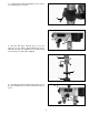
DRILL PRESS PARTS 5 1 7 6 9 8 2 3 4 10 13 11 12 Fig. 2 Fig. 1 Fig. 1 2 3 4 - Fig. 2 5 - Chuck 6 - Clamp Handle 7 - Pinon Shaft Handles (3) 8 - Table Raising and Lowering Handle 9 - M8x1.25x125mm Carriage Head Screws (2), 8.5mm Flat Washers (2), 8.5mm Lock Washers (2), M8x1.25 Hex Nuts (2), (for fastening the base to a supporting surface) 10 - Worm Gear for Table Raising and Lowering Mechanism 11 - Wrenches (one 3mm and one 5mm) 12 - M8x1.
ASSEMBLY FOR YOUR OWN SAFETY, DO NOT CONNECT THE MACHINE TO THE POWER SOURCE UNTIL THE MACHINE IS COMPLETELY ASSEMBLED AND YOU READ AND UNDERSTAND THE ENTIRE INSTRUCTION MANUAL. 1. Assemble the column (A) Fig. 3, to the base (B) using the four screws, three of which are shown at (C). Loosen set screw (D) and remove ring (E) and raising rack (F). E D F A C C B Fig. 3 G 2. Make certain worm gear (G) Figs. 4 and 5, is in place in table bracket (H) as shown. H Fig. 4 H G Fig. 5 3.
F 4. Slide raising rack (F) Fig. 7, table and table bracket onto drill press column, as shown. Make sure bottom of raising rack (F) Fig. 8, is inside the flange (J) on drill press base. Fig. 7 F J 5. Re-assemble ring (E) Fig. 9, which was removed in STEP 1. IMPORTANT: Bottom of ring (E) MUST NOT be pushed all the way down onto top of raising rack (F). MAKE SURE top of raising rack (F) is under bottom of ring (E) and that there is enough clearance to allow rack (F) to rotate around the column.
7. Thread stud on clamp handle (M) Fig. 12, into hole in rear of table bracket, as shown. M Fig. 12 N O 8. Place the drill press head (N) Fig. 13, onto the column as far as it will go. Align head (A) Fig. 13A, to table (B), and base (C). Tighten the two head locking screws (O) Fig. 13, with wrench supplied. Fig. 13 A B C Fig. 13A 9. Thread the three pinion shaft handles (P) Fig. 14, into the three tapped holes located in the pinion shaft, as shown. P Fig.
. IMPORTANT: Make certain the spindle taper (Q) Fig. 15, and tapered hole in chuck (R) are clean and free of any grease, lacquer or rust preventive coatings. NOTE: Household oven cleaner can effectively remove any substance from the spindle and chuck; however, carefully follow the manufacturer's safety rules concerning its use. Q R 11. IMPORTANT: Open the chuck jaws as wide as possible by turning the chuck sleeve (S) Fig. 16. Fig. 15 12.
FLEXIBLE LAMP A The flexible lamp operates independently of the drill press. To turn the lamp “ON” and “OFF”, rotate switch (A) Fig. 18A. To reduce the risk of fire, use 40 watt or less, 120 volt, reflector track type light bulb (not supplied). A standard household light bulb should not be used. The reflector track type light bulb should not extend below the lamp shade. Fig. 18A TABLE ADJUSTMENTS 1. The table can be raised or lowered on the drill press column by loosening the table clamp (A) Fig.
VARIABLE SPEED CONTROL A To avoid damaging the drive belts and pulleys, DO NOT turn speed control handles (A) Fig. 24, unless motor is running. The pilot wheel handles (A) are turned clockwise to increase speed and counterclockwise to decrease speed. The speed range is 500 rpm to 3100 rpm. A DRILLING HOLES TO DEPTH Fig. 24 Where a number of holes are to be drilled to exactly the same depth, the stop nut (A) Fig. 25, on the threaded stop rod (B) is used as follows: DISCONNECT MACHINE FROM POWER SOURCE.
ADJUSTING SPINDLE RETURN SPRING The spindle is automatically returned to its upper most position when the handle is released. It is recommended that the handle be allowed to slowly return to the top position after each hole has been drilled in the material. This spring has been properly adjusted at the factory and should not be disturbed unless absolutely necessary. To adjust the return spring, proceed as follows: DISCONNECT MACHINE FROM POWER SOURCE. 1. Loosen nuts (B) and (E) Fig. 27.
INSTALLING AND REMOVING DRILL BITS C DISCONNECT MACHINE FROM POWER SOURCE. B 1. Insert smooth end of drill bit (A) Fig. 29, into chuck (B), as far as it will go, and then back the bit out 1/16", or up to the flutes for small bits. A D 2. Make certain that the drill bit (A) Fig. 29, is centered in the chuck (B) before tightening the chuck with the key (C). Fig. 29 3. Turn the chuck key (C) Fig. 29, clockwise to tighten and counterclockwise to loosen the chuck jaws. 4.
MAINTENANCE LUBRICATION DISCONNECT MACHINE FROM POWER SOURCE. A 1. Remove the six screws (A) Fig. 30 that hold the top cover in place, and remove the top cover. A 2. The variable speed pulleys should be oiled weekly with a few drops of light machine oil in the two oil holes (B) Fig. 31, located on top of the variable speed pulleys. Fig. 30 Oil the holes when the drill press is turned OFF. Then turn the machine ON and run through the low and high speed ranges a few times. B B Fig.
ACCESSORIES A complete line of accessories is available from your Delta Supplier, Porter-Cable • Delta Factory Service Centers, and Delta Authorized Service Stations. Please visit our Web Site www.deltamachinery.com for a catalog or for the name of your nearest supplier. Since accessories other than those offered by Delta have not been tested with this product, use of such accessories could be hazardous. For safest operation, only Delta recommended accessories should be used with this product.
PORTER-CABLE • DELTA SERVICE CENTERS (CENTROS DE SERVICIO DE PORTER-CABLE • DELTA) Parts and Repair Service for Porter-Cable • Delta Machinery are Available at These Locations (Obtenga Refaccion de Partes o Servicio para su Herramienta en los Siguientes Centros de Porter-Cable • Delta) ARIZONA Tempe 85282 (Phoenix) 2400 West Southern Avenue Suite 105 Phone: (602) 437-1200 Fax: (602) 437-2200 CALIFORNIA Ontario 91761 (Los Angeles) 3949A East Guasti Road Phone: (909) 390-5555 Fax: (909) 390-5554 San Leandro