Instruction manual Model ESPAÑOL: PÁGINA 29 FRANÇAIS: PAGE 57 Generator H1000IS To learn more about Porter-Cable visit our website at: http://www.porter-cable.com IMPORTANT Please make certain that the person who is to use this equipment carefully reads and understands these instructions before starting operations. The Model and Serial No. plate is located on the frame. Record these numbers in the spaces below and retain for future reference. Model No. Type Serial No.
SAFETY GUIDELINES / DEFINITIONS This manual contains information that is important for you to know and understand. This information relates to protecting YOUR SAFETY and PREVENTING EQUIPMENT PROBLEMS. To help you recognize this information, we use the symbols below. Please read the manual and pay attention to these sections. indicates an imminently hazardous situation which, if not avoided, will result in death or serious injury.
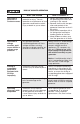
RISK OF ELECTROCUTION AND FIRE (Continued) HAZARD WHAT CAN HAPPEN HOW TO PREVENT IT Attempting to connect generator directly to the electrical system of any building structure. (Continued) Attempting to connect to the incoming utility service could result in electrocution. Restoration of electrical service while the generator is connected to the incoming utility could result in a fire or serious damage if an isolator switch is not installed.
RISK OF ELECTROCUTION AND FIRE (Continued) HAZARD Operation of unit when damaged, or with guards or panels removed. WHAT CAN HAPPEN HOW TO PREVENT IT Attempting to use the unit when it has been damaged, or when it is not functioning normally could result in fire or electrocution. Do not operate generator with mechanical or electrical problem. Have unit repaired by an Authorized Service Center. Removal of guarding could expose electrically charged components and result in electrocution.
RISK OF FIRE (Continued) HAZARD WHAT CAN HAPPEN HOW TO PREVENT IT Overfilling the fuel tank – fuel spillage. Spilled fuel and its vapors can become ignited from hot surfaces or sparks. Use care in filling the tank to avoid spilling fuel. Make sure fuel cap is secured tightly and check engine for fuel leaks before starting engine. Move generator away from refueling area or any spillage before starting engine. Allow for fuel expansion. Keep maximum fuel level ¼ inch below the tip of the fuel tank.
RISK OF UNSAFE OPERATION HAZARD WHAT CAN HAPPEN HOW TO PREVENT IT Operation of generator in careless manner All sources of energy include the • Review and understand all of potential for injury. Unsafe the operating instructions and operation or maintenance of your warnings in this manual. generator could lead to serious • Become familiar with the operinjury or death to you or others. ation and controls of the generator. Know how to shut it off quickly.
RISK OF HOT SURFACES HAZARD Contact with hot engine and generator components. WHAT CAN HAPPEN HOW TO PREVENT IT Contact with hot surfaces, such as engines exhaust components, could result in serious burns. During operation, touch only the control surfaces of the generator. Keep children away from the generator at all times. They may not be able to recognize the hazards of this product. RISK OF MOVING PARTS HAZARD Contact with moving parts can result in serious injury.
CONSUMER GENERAL AND SERVICE INFORMATION • Please read and follow these instructions for proper use and maintenance. • If you experience any problems and need assistance, please call us at our toll free number 1-888-559-8550, Monday through Saturday. • If repair or service part purchase is required, our many Authorized Warranty Service Centers are conveniently located and equipped to handle all inwarranty and out-of-warranty service.
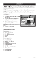
ASSEMBLY Read this manual. Do not attempt to operate equipment until you have read this Manual for Safety, Operation, and Maintenance Instructions. NOTE: This manual is a general manual. Information in this manual may or may not pertain to your model. Please read carefully. NOTE: Left and right describes the location of a part with the operator facing the outlet panel. UNPACKING 1. Locate the parts carton and set aside for later use. 2.
1. Lift the gas tank end of generator and slide 2x4 between generator and pallet as shown. The generator is too heavy to be lifted by one person. Obtain assistance from others before lifting. Gas Tank 2x4 2. Place handle grips on handle assemblies. Handle Grip 3. Place one 5/8” washer into the bottom of each end cap. Push end caps onto the end of the handle assemblies. End Cap Handle Assembly 5/8” Washer 4. Attach handle assemblies to frame using four screws and flange nuts.
5. Lift generator and remove 2x4. 6. Lift other end of generator and place two 2x4s between generator and pallet as shown. 7. 2x4 On the muffler side of the engine, remove cap screws Cap and flange nuts holding the heat shield to the frame. Screw Reassemble cap screws, heat shield, wheel bracket, and flange nuts and as shown. Tighten securely. Muffler Heat Shield Wheel Bracket Flange Nuts 8. On other side, assemble wheel bracket using cap screws and flange nuts supplied. Tighten securely.
ASSEMBLE SKYHOOK Tools needed: 1 - 1/2” socket or open end wrench 1 - 3/8" socket 1 - Torque wrench Parts bag contains: 1 - Skyhook 2 - Upper brackets 4 - Bolts, 5/16-18 x 7/8” 4 - Lockwashers, 5/16” 4 - Nuts, Whizlock 5/16” 1. Close fuel shut-off valve on tank by turning clockwise until it stops. 2. Remove four screws, and washers securing fuel tank to frame. Save screws and washers for reassembly. 3. Carefully place fuel tank inside frame rails as shown. 4. Place skyhook under frame as shown.
5. Place skyhook on the fuel tank side of the frame and install upper bracket as shown. 6. Wrap upper bracket around frame. Slide lockwashers onto bolts, insert through brackets, and secure with whizlock nuts. NOTE: DO NOT tighten bolts at this time. Repeat steps 5-7 on other side. 7. 8. 9 Position skyhook between arrows on label. NOTE: Bracket should not overlap onto weld (a).
BATTERY INSTALLATION The generator is equipped with a maintenance free battery. 1. For packaging purposes the black Wire Tie negative battery cable and battery were secured with wire ties. Cut Negative Battery Cable these wire ties. 2. Connect black negative cable to negative (-) battery post. Tighten securely. NOTE: Make sure rubber boot is covering positive (+) battery terminal. NOTE: If battery needs to be charged, follow these instructions. Wire Tie When charging the battery, do not smoke.
OBTAINING ELECTRICITY FROM THE GENERATOR There are basically 2 ways to obtain electricity from a generator: 1. Use of extension cords directly from the generator to the appliance, lights, tools, etc. 2. Use of a double-throw transfer switch installed directly to the main electrical supply outside of house.
OTHER LOOSE PARTS 1. Oil is supplied, see engine operator’s manual for correct procedure to add oil and fuel to engine. 2. The locking plugs maybe used when needed or required. The locking plugs are to be installed and/or used in accordance with appropriate local electrical code regulations. Refer to instructions enclosed with each plug for proper installation. 3. 12V DC cables to be used with the 12V DC outlets. See Operation section.
IDLE CONTROL Choose the correct application. 1. For normal application such as power tools, small electric appliances, light bulbs, and radios: Place the idle control switch in the ON position. The generator will idle down when there is no load. This lowers the engine noise, saves on fuel consumption, and engine life. 2. Idling down IS NOT recommend on large motors (refrigerators, freezers, etc) or voltage sensitive electronic equipment (computers, televisions, etc).
Never fill fuel tank indoors. Never fill fuel tank when engine is running or hot. Do not smoke when filling fuel tank. Never run engine indoors or in enclosed, poor ventilated areas, engine exhaust contains carbon monoxide, an odorless and deadly gas. 3. Make sure generator is grounded in accordance with local requirements. 4. All electrical loads MUST be disconnected. 5. Idle control switch must be in the OFF position. 6. Make sure skyhook bolts are tightened and torqued to 11-12 ft.-lbs. (132-144 in.-lbs.
4. Voltage sensitive equipment should be the last equipment connected to the generator. Plug voltage sensitive appliances such at TV's, VCR's, microwaves, ovens, computers, and cordless telephones into a UL listed voltage surge protector, then connect the UL listed voltage surge protector to the generator. Failure to connect and operate equipment in this sequence can cause damage to equipment and will void the warranty on your generator.
MAINTENANCE CUSTOMER RESPONSIBILITIES TABLE MAINTENANCE TASK Check oil level Before each use Every 25 Hours of Every Season X See Note 2 Clean Air Filter Assembly Prepare Unit for Storage Every 100 Hours of Every Season See Note 1 Change oil Check Spark Plug Every 50 Hours of Every Season X X X Prepare unit for storage if it is to remain idle for more than 30 days.
STORAGE If you are going to store your generator for more than 30 days, use the following information as a guide to prepare the generator for storage. Never store generator with fuel in the tank indoors or in enclosed, poorly ventilated areas, where fumes can reach an open flame, spark or pilot light as on a furnace, water heater, clothes dryer or other gas appliances. ENGINE PREPARATION 1. Add fuel stabilizer to fuel tank to minimize the formation of fuel gum deposits during storage. 2.
WATTAGE CALCULATIONS IMPORTANT Never exceed the rated capacity of your generator. Serious damage to the generator or appliance could result from an overload. 1. Starting and running wattage requirements should always be calculated when matching a generators wattage capacity to the appliance or tool. 2. There are two types of electrical appliances that can be powered by your generator: A. Items such as radios, light bulbs, television sets, and microwaves have a "resistive load".
3. The running wattage of examples 1 & 2 totals 1150 watts. The starting wattage of the small refrigerator is 2000 watts which is 1500 watts more than the running watts. Take this difference of 1500 starting watts from the refrigerator and add to the total running watts of 1150. Example 3: 1500 Starting Watts 1150 Running Watts TOTAL =2650 Total Watts Generator must have a maximum capacity of at least 2650 watts. STARTING WATTAGE REQUIREMENTS 1. 2. 3.
HOUSEHOLD WATTAGE CALCULATOR DEVICES WITH HIGH STARTING (INDUCTIVE)LOADS RUN WATTS TIMES (X) START FACTOR APPLIANCE OR LOAD DEVICE* TOTAL 800 x 3 REFRIGERATOR/ FREEZER = 2400 = 600 x 3 SMALL REFRIGERATOR = 1800 = 2400 x 3 AIR COND.
TROUBLESHOOTING GUIDE PROBLEM CORRECTION CAUSE Engine will not 1. start 2. 1. 2. Add fuel or oil. Turn to "ON" position 3. 4. 5. Replace spark plug. Adjust choke accordingly. Open fuel shut-off valve. 7. Low on fuel or oil. Ignition switch in "Off" position. Faulty spark plug. Choke in wrong position. Fuel shut-off valve in closed position Unit loaded during startup. Spark plug wire loose. 1. Faulty receptacle. 2. 3. Circuit breaker kicked out. Defective capacitor. 4. Faulty power cord. 5.
LIMITED WARRANTY PORTER-CABLE CORPORATION warrants to the original purchaser that all products covered under this warranty are free from defects in material and workmanship. Products covered under this warranty include air compressors, air tools, service parts, pressure washers, and generators, which have the following warranty periods: 3 YEARS - Limited warranty on 2-stage oil-free air compressor pumps that operate at 1725 RPM. 2 YEARS - Limited warranty on oil-lubricated air compressor pumps.
NOTES 27- ENG D28469
QUICK FACTS CALL 1-888-559-8550 TO FIND A LOCAL AUTHORIZED SERVICE CENTER NEAR YOU FOR REPAIRS AND SERVICE PART PURCHASES ENGINE GAS Use clean, fresh gasoline with a minimum 87 octane rating. Do not add gasoline during or immediately after use. Refer to engine owner's manual for oil recommendations. ENGINE OIL Most generators are equipped with a low-oil shutdown. If the oil is low or if the Generator is not level, the engine will not start. WATTAGE WIRING BATTERY VOLT REG.