0-IN PORTABLE TABLE SAW Français (#) Español (#) www.portercable.com Instruction Manual PCX362010 To reduce the risk of serious injury, thoroughly read and comply with all warnings and instructions in this manual and on product.
TABLE OF CONTENTS FUNCTIONAL DESCRIPTION................................................... 2 RIP CUTS........................................................................... 20 IMPORTANT SAFETY INSTRUCTIONS.................................... 2 BEVEL RIPPING................................................................. 20 SAFETY SYMBOL-DEFINITIONS........................................ 3 CROSSCUTTING...............................................................
SAFETY SYMBOLS- DEFINITIONS The definitions below describe the level of severity of each signal word. Please read the manual and pay attention to these symbols. Indicates an imminently hazardous situation which, if not avoided, will result in death or serious injury. Indicates a potentially hazardous situation which, if not avoided, could result in death or serious injury. Indicates a potentially hazardous situation which, if not avoided, may result in minor or moderate injury.
GENERAL POWER TOOL SAFETY RULES (CONTINUED) and heavy enough to carry the current your product will draw. An undersized cord will cause a drop in line voltage, resulting in loss of power and overheating. See Extension Cord Chart for correct size depending on cord length and data plate ampere rating. If in doubt, use the next smaller gauge number. The smaller the gauge number, the heavier the cord. When working outside, make sure the extension cord is rated for outdoor use.
TABLE SAW SAFETY RULES TERMINOLOGY The following terms will be used throughout the manual and you should become familiar with them. —— Through-cut - any cut that completely cuts through the workpiece. —— Non-through cut - any cut that does not completely cut through the workpiece. —— Push stick - a wooden or plastic stick, usually homemade, that is used to push a small workpiece through the saw and keeps the operator’s hands clear of the blade.
TABLE SAW SAFETY RULES fixtures or feather boards to help guide and control The workpiece. Accessories for use with your saw are available at extra cost from your local dealer or authorized service center. 16. DO NOT USE RIP FENCE AND MITER GAUGE AT THE SAME TIME. 17. AVOID AWKWARD OPERATIONS AND HAND POSITIONS where a sudden slip could cause a hand to move into a saw blade. Operate with table at or near waist level for maximum balance and control.
TABLE SAW SAFETY RULES (CONTINUED) KICKBACKS Kickbacks can cause serious injury. A kickback occurs when a part of the workpiece binds between the saw blade and the rip fence, or other fixed object, and rises from the table and is thrown toward the operator. The risk of kickback can be minimized by attention to the following instructions. • HOW TO REDUCE THE RISK OF KICKBACKS AND PROTECT YOURSELF FROM POSSIBLE INJURY: • • • • • Be certain that the rip fence is parallel to the saw blade.
POWER CONNECTIONS POWER SOURCE This saw is equipped with a 15-amp motor for use with a 120-volt, 60-HZ alternating current. See instructions below regarding proper connections for your saw. For voltage, the wiring in a shop is as important as the motor’s rating.
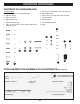
UNPACKING (CONTINUED) SHIPPING CONTENTS A. Saw I. B. Rip Fence J. Stand legs (4) C. Blade K. Blade Wrenches (on board storage) D. Anti-Kickback Pawls L. Push Stick E. Blade Guard M. Extension Wing F. N. Fence Rail Throat Plate G. Miter Gauge Stand Part 2 O. Riving Knife (preassembled to saw) H.
UNPACKING (CONTINUED) CONTENTS OF HARDWARE BAG Description (QTY) g. M5 x 10 mm (3/8 in.) Hex Socket Cap Screw (3) a. M8 x 35 mm (1 1/2 in.) Carriage Bolt (8) h. M5 Flat Washer (2) b. M8 Lock Nut (8) i. M5 x 25 mm (1 in.) Hex Socket Cap Screw (6) c. M8 Lock Nut (2) j. Shoulder Screw d. M8 Flat Washer (2) k. M5 Kep Nut (2) e. M8 Plastic Washer (2) l. f. m. Knob M8 x 65 mm (2 9/16 in.
GENERAL PARTS KNOWLEDGE RIVING KNIFE ANTI-KICKBACK PAWLS BLADE GUARD THROAT PLATE TABLE FENCE LOCK MITER GAUGE RIP FENCE SCALE EXTENSION WING FENCE RAIL PUSH STICK HEIGHT ADJUSTMENT WHEEL HEX/PHILLIPS WRENCH BEVEL SCALE ON/OFF SWITCH BLADE WRENCHES BEVEL LOCK STAND ASSEMBLY The part and hardware names and letters correspond to those used in General Parts Knowledge on Page 11 and the Shipping Contents on page 9 & 10.
ASSEMBLY (CONTINUED) NOTE: Please refer to (Fig. 2) for correct stand cross section parts setup. H H I I CORRECT INCORRECT FIG. 2 With assembled cross section stand open, attach legs (J) to the stand using (8) M8 x 35mm (1 1/2 in.) carriage bolts (a) and (8) M8 lock nuts (b). Tighten lock nuts to secure legs to stand. (See Fig. 3) J b NOTE: Do not over tighten lock nuts. a See finished assembly of stand in Fig. 4. FIG. 3 J FIG.
ASSEMBLY (CONTINUED) ATTACHING STAND TO SAW Place saw (A) on stand assembly while aligning wing screws with threaded holes in saw base. See Fig. 6 and 6a. A Tighten wing screws to secure stand assembly to saw (A). a NOTE: Do not over tighten. STAND ASSEMBLY FIG. 6 Saw as assembled shown in Fig. 7. FIG. 7 FENCE RAIL AND EXTENSION WING ASSEMBLY Attached extension wing (M) to the table with (3) M5 x 10mm (3/8 in.) hex socket cap screws (g) and (2) M5 flat washers (h) as shown in Fig. 8.
ASSEMBLY (CONTINUED) Insert (2) remaining M5 x 25mm (1 in.) hex socket cap screws (i) through the fence rail (N) and extension wing (M) and secure with (2) M5 kep nuts (k) as shown in Fig. 10. Use straightedge to ensure extension wing is level as shown in Fig. 10a and 10b. N i a k M b FIG. 10 HEIGHT ADJUSTMENT KNOB INSTALLATION m 1. Insert shoulder screw (j) into height adjustment knob (m) as shown in Fig. 11. 2. Tighten shoulder screw with Phillips Screw driver into Hand Wheel.
ASSEMBLY (CONTINUED) POSITION THE RIVING KNIFE A riving knife is a flat plate that fits into the cut made by the saw blade (the “kerf”). It is intended to reduce the risk of kickback by holding the kerf open and lessening the tendency of the workpiece to pinch the blade. UP O a To reduce the risk of serious injury, • • • • the riving knife must be installed for every through cut and for every non-through cut unless the riving knife would interfere with the cut.
ASSEMBLY (CONTINUED) If adjustment is needed, remove the throat plate and adjust the (4) Phillips set screws (Fig. 16a) up or down as needed. See Fig. 16. Replace throat plate and recheck. Repeat this process as needed until the throat plate is level. • a It is important that the throat plate is properly adjusted to the table. This ensures that the work piece is not caught on the throat plate or the table when feeding the work piece through the blade during a cut. FIG.
ASSEMBLY (CONTINUED) RIP FENCE Position rip fence (B) over the table as shown in Fig. 19. Lower rip fence (B) over front of rail on the front of the saw and back of the table as shown in Fig. 19a. Engage lock on the rip fence after placing fence in desired location on the table. See Fig. 19b. B a Check to ensure that the rip fence is secured to the table prior to use when making a cut.
OPERATION Failure to comply with the following warnings may result in serious personal injury. READ ENTIRE MANUAL. In addition to reading these operating instructions, it is important to read and understand the entire manual before operating this saw. Follow all applicable instructions regarding assembly, preparation, and adjustment prior to making any cuts and comply with all safety rules and warnings in this section and elsewhere throughout this manual. 1.
MAKING CUTS Failure to comply with the following warnings may result in serious personal injury. • • • • Never touch the free end of the workpiece or a free piece that is cut off, while the power is on and/or the saw blade is rotating. Blade contact or binding may occur, resulting in a thrown workpiece When sawing a long workpiece or a panel, use a work support, such as a sawhorse, rollers or outfeed table at the same height as the table surface of the saw.
MAKING CUTS (CONTINUED) RIP CUTS 1. 2. 3. 4. 5. 6. 7. 8. 9. 10. 11. 12. Remove miter gauge Make sure bevel angle is set to 0°. Set blade to correct height for workpiece. Install rip fence and lock it down parallel with and at desired distance from blade. Keep fingers at least 6 inches from the blade at all times. When the hand cannot be safely put between the blade and the rip fence, select a larger workpiece, or use a push stick and other cutting aids, as needed, to control the workpiece.
MAKING CUTS (CONTINUED) CROSSCUTTING NEVER use the fence as a guide or length stop when crosscutting. • The cut-off piece must never be confined in any through-sawing (cutting completely through the workpiece) operation—to prevent pinching blade which may result in a thrown workpiece and possibly injury. • When using a block as a cut-off gauge, the block must be at least 3/4-inch (19mm) thick.
MAKING CUTS (CONTINUED) COMPOUND MITER CUTS This is a combination of bevel crosscutting and mitering. Refer to Figure 26 and follow the instructions for both bevel crosscutting and mitering. Remember to use the right miter slot on the right side of the blade for all bevel cuts. 5 LARGE PANEL CUTS 9 Place workpiece supports at the same height as the saw table behind saw to support the cut workpiece, and alongside (s) of saw, as needed.
CUTTING AIDS AND ACCESSORIES PUSH STICK In order to operate your table saw safely, you must use a push stick whenever the size or shape of the workpiece would otherwise cause your hands to be within 6-inches (152mm) of the saw blade or other cutter. A push stick is included with this saw. No special wood is needed to make additional pushsticks as long as it is sturdy and long enough with no knots, checks or cracks.
CUTTING AIDS AND ACCESSORIES (CONTINUED) AUXILIARY MITER GAUGE FACING An auxiliary miter gauge facing is used to increase the surface area of the miter gauge face. If desired, you can fit the miter gauge with an auxiliary wood facing that should be at least 1-inch (25mm) higher than the maximum depth of cut, and at least as wide as the miter gauge.
CUTTING AIDS AND ACCESSORIES (CONTINUED) FEATHERBOARD Featherboards are used to keep the workpiece in contact with the fence and table (Figure 30), and help prevent kickback. Featherboards are especially useful when ripping small workpieces and for completing non-through cuts. The end is angled with a series of narrow slots to give a friction hold on the workpiece, It is locked in place on the table or fence with a c-clamp.
MAKING ADJUSTMENTS LEVELING THE THROAT PLATE Check that the throat plate is properly adjusted to the table. Front of throat plate should be level or slightly below the surface of the table and rear of the throat plate should be level or slightly above the surface of the table. See Fig. 15. There are four phillips set screws (A) pre-assembled to the table that are used to level the throat plate. (See Fig.
MAKING ADJUSTMENTS (CONTINUED) ADJUSTING THE BLADE HEIGHT For all through cuts, the top of the blade points should be above the workpiece and the bottom of the blade gullets are below the top surface of workpiece. ADJUSTMENT WHEEL For non-through cuts, the top of the blade points should be set to the depth of the cut. To adjust the height of the blade, refer to Figure 34 and do the following: Make sure the bevel lock lever is in the locked (down) position.
RIVING KNIFE ALIGNMENT Your riving knife may be out of alignment if your work piece is hitting the riving knife after the cut or causing some binding during the cut. When this condition occurs you will need to make an adjustment to the riving knife alignment. The following procedures in this section will assist you with making adjustments to the riving knife alignment. NON-THRU CUT POSITION THRU-CUT POSITION AA BB3 BB2 Locating point for THRU CUT POSITION as shown in Fig.
MAINTENANCE To reduce the risk of injury, turn unit off and disconnect it from power source before cleaning or servicing, before installing and removing accessories, before adjusting and when making repairs. An accidental start-up can cause injury. KEEP MACHINE CLEAN Periodically blow out all air passages with dry compressed air. All plastic parts should be cleaned with a soft damp cloth. NEVER use solvents to clean plastic parts. They could possibly dissolve or otherwise damage the material.
WARRANTY THREE-YEAR LIMITED WARRANTY PORTER CABLE® MODEL PCX362010 TABLE SAW PORTER-CABLE will either repair or replace this product, without charge, if it has any defects due to faulty materials or workmanship for three years from the date of purchase. This warranty does not cover part failure due to normal wear or tool abuse, products purchased in used or damaged condition or from a retailer located outside the United States or Canada.
NOTES 31
2651 New Cut Rd. Spartanburg, SC 29303 1-844-816-8986 www.portercable.