
Operating Guide

15
a
b
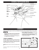
ASSEMBLY (CONTINUED)
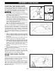
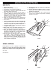
INSERT AND LEVEL THROAT
PLATE
POSITION THE RIVING KNIFE
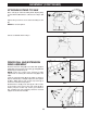
Insert the rear tab of the throat plate (the end with the
wear plates) under the surface of the table, and snap
the front end in place, as shown in Fig. 14.
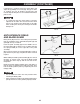
Check that the throat plate is properly adjusted to the
table. Front of throat plate should be level or slightly
below the surface of the table and rear of the throat
plate should be level or slightly above the surface of
the table. See Fig. 15.
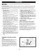
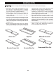
A riving knife is a flat plate that fits into the cut made by
the saw blade (the “kerf”). It is intended to reduce the
risk of kickback by holding the kerf open and lessening
the tendency of the workpiece to pinch the blade.
To reduce the risk of serious injury,
• the riving knife must be installed for every through
cut and for every non-through cut unless the riving
knife would interfere with the cut.
• always use a blade with the correct thickness to
match the riving knife. (0.10” (2.6mm) min. kerf
width and 0.73” (1.85mm) max body thickness)
• The riving knife must be securely positioned in the
“up” or “through cut” position when using the anti-
kickback pawls and blade guard.
• Make sure the riving knife is properly aligned to the
blade. (See Riving Knife Alignment, page 27)
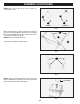
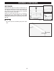
This saw is shipped with its riving knife (O) installed
in the lowered or “non-through cut” position. This
riving knife matches the thickness of the blade that
is shipped with your saw. To install the anti-kickback
pawls and the blade guard assembly, first raise the
riving knife from the lowered or “non-through cut”
position to the raised or “through cut position,” as
follows:
1. With the blade assembly to the highest possible
position, carefully reach alongside the blade and
raise the riving knife locking lever up to unlock the
riving knife.
2. Gently move the riving knife to the right to release it
from the lock pins in the riving knife assembly.
3. Slide the riving knife up and forward until you feel
the lock pins engage the riving knife in the “through
cut” position. When properly aligned in this
position, the “thru cut position” line on the riving
knife will be parallel to and level with the table.
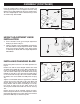
4. Return the riving knife lock lever to the lock
position.
5. Make sure the riving knife is securely installed and
properly aligned with the blade.
NOTE: For non-through cuts, lower the riving knife
to the “non-through cut” position using the same
procedure. In this case the “non-thru cut position” line
should be parallel to and level with the table.
FIG. 15
FIG. 14
FIG. 13
LOCK
LEVER
WEAR
PLATE
UP
THROUGH
CUT
POSITION
O