
Use and Care Manual

DUTY CYCLE
This air compressor pump is capable of running continuously. However, to prolong the life of
your air compressor, it is recommended that a 50%-75% average duty cycle be maintained;
that is, the air compressor pump should not run more than 30-45 minutes in any given hour.
ASSEMBLY
UNPACKING
Remove unit from carton and discard all packaging.
INSTALLATION
HOW TO SET UP YOUR UNIT
Location of the Air Compressor
• Locatetheaircompressorinaclean,dryandwellventilatedarea.
• Theaircompressorshouldbelocatedatleast12"(30.5cm)awayfromthewallorother
obstructions that will interfere with the flow of air.
• Theaircompressorpumpandshroudaredesignedtoallowforpropercooling.The
ventilation openings on the compressor are necessary to maintain proper operating
temperature. Do not place rags or other containers on or near these openings.
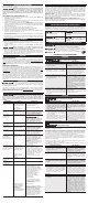
GROUNDING INSTRUCTIONS (FIG. 1)
RISK OF ELECTRICAL SHOCK. In the event of a short circuit,
grounding reduces the risk of shock by providing an escape wire for the electric
current. This air compressor must be properly grounded.
The portable air compressor is equipped with a cord having a grounding wire with an
appropriate grounding plug (A).
1. The cord set and plug (A) with this unit contains a grounding pin (B). This plug MUST be
used with a grounded outlet (C).
IMPORTANT: The outlet being used must be installed and grounded in accordance with all
local codes and ordinances.
2. Make sure the outlet being used has the same configuration as the grounded plug. DO
NOT USE AN ADAPTER. See figure 1.
3. Inspect the plug and cord before each use. Do not use if there are signs of damage.
4. If these grounding instructions are not completely understood, or if in doubt as to
whether the compressor is properly grounded, have the installation checked by a
qualified electrician.
RISK OF ELECTRICAL SHOCK. IMPROPER GROUNDING CAN RESULT
IN ELECTRICAL SHOCK.
Do not modify the plug provided. If it does not fit the available outlet, a correct outlet
should be installed by a qualified electrician.
Repairs to the cord set or plug MUST be made by a qualified electrician.
EXTENSION CORDS
If an extension cord must be used, be sure it is:
• a3-wireextensioncordthathasa3-bladegroundingplug,anda3-slotreceptaclethat
will accept the plug on the product
• ingoodcondition
• nolongerthan50'(15.2m)
• 14gauge(AWG)orlarger.(Wiresizeincreasesasgaugenumberdecreases.12AWG
and10AWGmayalsobeused.DONOTUSE16OR18AWG.)
Risk of Property Damage. The use of an undersized extension cord will
cause voltage to drop resulting in power loss to the motor and overheating. Instead of using
an extension cord, increase the working reach of the air hose by attaching another length of
hose to its end. Attach additional lengths of hose as needed.
VOLTAGE AND CIRCUIT PROTECTION
Refer to the Specification Chart for the voltage and minimum branch circuit
requirements.
Risk of Overheating. Certain air compressors can be operated on a 15 amp
circuit if the following conditions are met.
1. Voltage supply to circuit must comply with the National Electrical Code.
2. Circuit is not used to supply any other electrical needs.
3. Extension cords comply with specifications.
4. Circuit is equipped with a 15 amp circuit breaker or 15 amp time delay fuse.
NOTE: If compressor is connected to a circuit protected by fuses, use only time delay
fuses. Time delay fuses should be marked "D" in Canada and "T" in the US.
If any of the above conditions cannot be met, or if operation of the compressor repeatedly
causes interruption of the power, it may be necessary to operate it from a 20 amp circuit. It
is not necessary to change the cord set.
OPERATION
KNOW YOUR AIR COMPRESSOR
READTHISOWNER’SMANUALANDSAFETYRULESBEFOREOPERATINGYOURUNIT.
Compare the illustrations with your unit to familiarize yourself with the location of various
controls and adjustments. Save this manual for future reference.
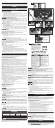
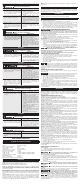
DESCRIPTION OF OPERATION (FIG. 2–4)
Become familiar with these controls before operating the unit.
On(I)/Off(O) Switch (D): Place this switch in the On (I) position to provide automatic power
to the pressure switch and Off (O) to remove power at the end of each use.
Pressure Switch (not shown): The pressure switch automatically starts the motor when
the air tank pressure drops below the factory set "cut-in" pressure. It stops the motor
when the air tank pressure reaches the factory set "cut-out" pressure.
Safety Valve (H): If the pressure switch does not shut off the air compressor at its "cut-
out" pressure setting, the safety valve will protect against high pressure by "popping out"
at its factory set pressure (slightly higher than the pressure switch "cut-out" setting).
Tank Pressure Gauge (I): The tank pressure gauge indicates the reserve air pressure in
the tank.
Outlet Pressure Gauge (E): The outlet pressure gauge indicates the air pressure available
at the outlet side of the regulator. This pressure is controlled by the regulator and is always
less than or equal to the tank pressure.
Regulator (G): Controls the air pressure shown on the outlet pressure gauge. Turn regu-
lator knob clockwise to increase pressure and counterclockwise to decrease pressure.
Cooling System (not shown): This compressor contains an advanced design cooling
system. At the heart of this cooling system is an engineered fan. It is perfectly normal for
this fan to blow air through the vent holes in large amounts. You know that the cooling
system is working when air is being expelled.
Air Compressor Pump (not shown): Compressesairintotheairtank.Workingairisnot
available until the compressor has raised the air tank pressure above that required at the
air outlet.
Drain Valve (K): The drain valve is located at the base of the air tank and is used to drain
condensation at the end of each use.
Check Valve (M):Whentheaircompressorisoperating,thecheckvalveis"open",allowing
compressedairtoentertheairtank.Whentheaircompressorreaches"cut-out"pressure,
the check valve "closes", allowing air pressure to remain inside the air tank.
Motor Overload Protector (not shown): The motor has a thermal overload protector. If the
motor overheats for any reason, the overload protector will shut off the motor. The motor
must be allowed to cool down before restarting. To restart:
1. Set the On/Off lever to "Off" and unplug unit.
2. Allow the motor to cool.
3. Plug the power cord into the correct branch circuit receptacle.
4. Set the Auto/Off lever to "On" position.
Quick-Connect Body (F): The quick connect body accepts industrial quick connect plugs.
HOW TO USE YOUR UNIT (FIG. 2)
How to Stop
1. Set the On/Off switch (D) to "Off".
2. Unplug unit when not in use.
Before Starting
Do not operate this unit until you read this instruction manual for
safety, operation and maintenance instructions.
Before Each Start-Up
1. Set the On/Off switch (D) to "Off".
2.
Plug the power cord into the correct branch circuit receptacle.
(Refer to Voltage and
Circuit Protection paragraph in the Installation section of this manual.)
3. Turn the regulator knob (G) counterclockwise to set the outlet pressure to zero.
4. Attach hose and accessories.
Risk of unsafe operation. Firmly grasp air hose in hand when installing
or disconnecting to prevent hose whip.
Risk of unsafe operation. Do not use damaged or worn accessories.
NOTE: The hose or accessory will require a quick connect plug if the air outlet is equipped
with a quick connect body (F).
Risk of Bursting. Too much air pressure causes a hazardous risk of
bursting. Check the manufacturer’s maximum pressure rating for air tools and acces-
sories. The regulator outlet pressure must never exceed the maximum pressure rat-
ing.
Risk of property damage. Compressed air from the unit may contain wa ter
condensation and oil mist. Do not spray un fil tered air at an item that could be damaged by
moisture. Some air tools and accessories may require filtered air. Read the in struc tions for
the air tools and accessories.
How to Start
1. Set the On/Off switch (D) to "On" and allow tank pressure to build. Motor will stop when
tank pressure reaches "cut-out" pressure.
2. Turn regulator knob (G) clockwise to increase pressure and stop when desired pressure
is reached.
Risk of unsafe operation. If any unusual noise or vibration is noticed,
stop the compressor immediately and have it checked by a trained service technician.
The compressor is ready for use.
MAINTENANCE
CUSTOMER RESPONSIBILITIES
Before each use Daily or after
each use
See tank warning label
Check Safety Valve X
Drain Tank X
Remove tank from service X
1
1- For more information,
call our Customer Care Center at 1-(888)-848-5175
Risk of unsafe operation. Unit cycles automatically when power is on.
When performing maintenance, you may be exposed to voltage sources, compressed
air, or moving parts. Personal injuries can occur. Before performing any maintenance
or repair, disconnect power source from the compressor and bleed off all air pressure.
NOTE: See Operation section for the location of controls.
TO CHECK SAFETY VALVE (FIG. 2)
Risk of Bursting. If the safety valve does not work properly, over-
pressurization may occur, causing air tank rupture or an explosion.
Risk from Flying Objects. Always wear certified safety equipment:
ANSI Z87.1 eye protection (CAN/CSA Z94.3) with side shields.
Before starting compressor, pull the ring on the safety valve (H) to make sure that the safety
valve operates freely. If the valve is stuck or does not operate smoothly, it must be replaced
with the same type of valve.
TO DRAIN TANK (FIG. 2, 3)
Risk of Unsafe Operation. Air tanks contain high pressure air. Keep
face and other body parts away from outlet of drain. Use ANSI Z87.1 eye protection
(CAN/CSA Z94.3) when draining as debris can be kicked up into face.
Risk from noise. Always wear proper hearing protection during use.
Under some conditions and duration of use, noise from this product may contribute
to hearing loss.
NOTE: All compressed air systems generate condensate that accumulates in any drain
point (e.g., tanks, filter, aftercoolers, dryers). This condensate contains lubricating oil and/or
substances which may be regulated and must be disposed of in accordance with local, state,
and federal laws and regulations.
Risk of Bursting. Water will condense in the air tank. If not drained,
water will corrode and weaken the air tank causing a risk of air tank rupture.
Risk of Property Damage. Drain water from air tank may contain oil and rust
which can cause stains.
1. Set the On/Off switch (D) to "Off".
2. Turn the regulator knob (G) counterclockwise to set the outlet pressure to zero.
3. Remove the air tool or accessory.
4. Place a suitable container under the drain valve to catch discharge.
5. Pull ring on safety valve (H) allowing air to bleed from the tank until tank pressure is
approximately 20 psi. Release safety valve ring.
6. Drain water from air tank by opening drain valve (K) on bottom of tank.
7. After the water has been drained, close the drain valve. The air compressor can now
be stored.
NOTE: If drain valve is plugged, release all air pressure. The valve can then be removed,
cleaned, the reinstalled.
SERVICE AND ADJUSTMENTS
ALL MAINTENANCE AND REPAIR OPERATIONS NOT LISTED MUST BE PERFORMED
BY TRAINED SERVICE TECHNICIAN.
Risk of Unsafe Operation. Unit cycles automatically when power is on.
When servicing, you may be exposed to voltage sources, compressed air, or moving
parts. Before servicing unit unplug or disconnect electrical supply to the air compres-
sor, bleed tank of pressure, and allow the air compressor to cool.
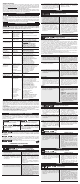
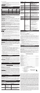
TO REPLACE REGULATOR (FIG. 5–8)
1. Release all air pressure from air tank. See To Drain Tank in the Maintenance section.
2. Unplug unit.
3. Using an adjustable wrench remove the gauges (E, I), quick connect (F), and safety
valve (H) from the regulator manifold (G).
4. Remove the hose by removing the hose clamp (L). NOTE: The hose clamp is not reus-
able. You must purchase a new hose clamp, see Replacement Parts in the Service
section or purchase a standard hose clamp at a local hardware store.
5. Remove pump mounting screws (O) securing pump (one on each side).
6. Carefully slide pump from brackets and out of the way.
7. Using an adjustable wrench remove the regulator manifold (G).
8. Apply pipe sealant to new regulator manifold and assemble, tighten with wrench.
9. Reapply pipe sealant to gauges, quick connect, and safety valve.
10. Reassemble all components in reverse order of removal. Make sure to orient gauges
to read correctly and use wrenches to tighten all components.
STORAGE
Before you store the air compressor, make sure you do the following:
1. Review the Maintenance section on the preceding pages and perform scheduled
maintenance as necessary.
2. Drain water from air tank. See To Drain Tank under Maintenance.
Water will condense in the air tank. If not drained, water will corrode
and weaken the air tank causing a risk of air tank rupture.
3. Protect the electrical cord and air hose from damage (such as being stepped on or run
over).Windairhoselooselyaroundthecompressorhandle.Wrapelectricalcordonto
the cord wrap.
4. Store the air compressor in a clean and dry location.
SERVICE
REPLACEMENT PARTS
Use only identical replacement parts. For a parts list or to order parts, visit our service
website at http://servicenet.portercable.com/. You can also order parts from your nearest
PORTER-CABLEFactoryServiceCenterorPORTER-CABLEAuthorizedWarrantyService
Center. Or, you can call our Customer Care Center at 1-(888)-848-5175.
UNE UTILISATION INCORRECTE PEUT ÊTRE DANGEREUSE.
SUIVEZ LES INSTRUCTIONS CI-DESSOUS :
RISQUE D'ECLATEMENT. ASSUREZ-VOUS QUE LA PRESSION DE
SORTIE DU COMPRESSEUR EST RÉGLÉE À UN NIVEAU INFÉRIEUR À
LA PRESSION D'UTILISATION MAXIMUM DU PISTOLET
VAPORISATEUR OU DE L'ACCESSOIRE. AVANT DE DÉMARRER LE
COMPRESSEUR, TIREZ SUR L'ANNEAU DE LA SOUPAPE DE SÛRETÉ
POUR VOUS ASSURER QU'ELLE FONCTIONNE LIBREMENT.
VIDANGEZ L'EAU DU RÉSERVOIR À AIR APRÈS CHAQUE UTILISATION.
RISQUE D'INCENDIE OU D'EXPLOSION. NE PAS VAPORISER UN
LIQUIDE OU UN PEINTURE INFLAMMABLE OU COMBUSTIBLE PRÈS
D'ÉTINCELLES, DE FLAMMES, DE VEILLEUSES NI DANS UN ENDROIT
RESTREINT OU RENFERMÉ. L'AIRE DE VAPORISATION DOIT ÊTRE
BIEN AÉRÉE. GARDEZ LE COMPRESSEUR À UNE DISTANCE D'AU
MOINS 20 PIEDS DE LA SURFACE À VAPORISER. NE PORTEZ PAS LE
COMPRESSEUR ET NE L'UTILISEZ PAS NI AUCUN AUTRE APPAREIL
ÉLECTRIQUE À PROXIMITÉ DE L'AIRE DE VAPORISATION. NE FUMEZ
JAMAIS QUAND VOUS VAPORISEZ. UTILISEZ UN FLEXIBLE D'AIR
D'UNE LONGUEUR MINIMUM DE 25 PIEDS POUR RELIER LE
PISTOLET VAPORISATEUR AU COMPRESSEUR.
RISQUE DE DANGER CORPOREL. NE DIRIGEZ JAMAIS UN JET
D'AIR COMPRIMÉ OU DE LIQUIDE VERS VOTRE CORPS.
RISQUE DE CHOC ÉLECTRIQUE. N'EXPOSEZ PAS LE
COMPRESSEUR À LA PLUIE. REMISEZ-LE À L'INTÉRIEUR.
LISEZ LE MANUEL DE L'UTILISATEUR POUR DES
INSTRUCTIONS COMPLÈTES CONCERNANT LA SÉCURITÉ,
L'UTILISATION ET LES RÉPARATIONS.
RUSTED TANK CAN CAUSE
EXPLOSION AND SEVERE
OR FATAL INJURY.
TILT TANK FORWARD TO
DRAIN AFTER EACH USE.
EL TANQUE OXIDADO PUEDE CAUSAR
EXPLOSIÛN HERIDAS SERIAS O
FATALES.
INCLINAR EL TANQUE HACIA ADELANTE
PARA DRENAR DESPUÈS DE CADA USO.
UN RÈSERVOIR ROUILLÈ PEUT PROVOQUER
UNE EXPLOSION ET CAUSER DES
BLESSURES GRAVES OU FATALES.
INCLINEZ LE RÈSERVOIR VERS L'AVANT POUR
LE VIDANDER APRËS CHAQUE UTILISATION.
INCORRECT USE CAN CAUSE HAZARDS. FOLLOW THESE INSTRUCTIONS:
RISK OF BURSTING.
MAKE SURE THE COMPRESSOR OUTLET PRESSURE IS SET
LOWER THAN THE MAXIMUM OPERATING PRESSURE OF THE SPRAY GUN OR TOOL.
BEFORE STARTING THE COMPRESSOR, PULL THE RING ON THE SAFETY VALVE TO
MAKE SURE THE VALVE MOVES FREELY. DRAIN WATER FROM TANK AFTER EACH USE.
RISK OF FIRE OR EXPLOSION.
DO NOT SPRAY A FLAMMABLE OR COMBUSTIBLE
LIQUID OR PAINT NEAR SPARKS, FLAMES, PILOT LIGHTS, OR IN A CONFINED AREA. THE
SPRAY AREA MUST BE WELL VENTILATED. KEEP COMPRESSOR AT LEAST 20 FEET AWAY
FROM SPRAY AREA. DO NOT CARRY AND OPERATE THE COMPRESSOR, OR ANY OTHER
ELECTRICAL DEVICE NEAR THE SPRAY AREA. NEVER SMOKE WHEN SPRAYING. USE A
MINIMUM OF 25 FEET OF HOSE TO CONNECT A SPRAY GUN TO THE COMPRESSOR.
RISK OF PERSONAL INJURY.
NEVER SPRAY COMPRESSED AIR OR MATERIAL AT THE BODY.
RISK OF ELECTRICAL SHOCK.
DO NOT EXPOSE TO RAIN. STORE INDOORS.
READ OWNER'S MANUAL FOR COMPLETE SAFETY, OPERATION, AND
REPAIR INSTRUCTIONS.
HOT SURFACE. RISK OF
BURNS. DO NOT TOUCH.
SUPERFICIE CALIENTE.
RIESGO DE QUEMADURAS.
NO TOCAR.
SURFACE TRÈS CHAUDE.
RISQUES DE BRÛLURES.
NE PAS TOUCHER.
EL USO INDEBIDO PUEDE GENERAR RIESGOS. SEGUIR ESTAS
INSTRUCCIONES:
RIESGO DE ESTALLIDO. ASEGÚRESE QUE LA VÁLVULA DE SALIDA
DEL COMPRESOR ESTE REGULADA POR DEBAJO DEL MÁXIMO DE
LA PRESIÓN DE OPERACIÓN DE LA PISTOLA ROCIADORA O
HERRAMIENTA. ANTES DE ARRANCAR EL COMPRESOR, TIRAR DEL
ANILLO EN LA VÁLBULA DE SEGURIDAD PARA ASEGURARSE QUE LA
VÁLVULA SE MUEVE LIBREMENTE. DRENAR EL AGUA DEL TANQUE
DESPUÉS DE CADA USO.
RIESGO DE FUEGO O EXPLOSIÓN. NO ROCIAR LÍQUIDO NI
PINTURAS INFLAMABLES O COMBUSTIBLES CERCA DE CHISPAS,
LLAMAS, LLAMAS DE PILOTO O EN ÁREAS CERRADAS. EL ÂREA DE
TRABAJO DEBE ESTAR BIEN VENTILADA. MANTENER EL
COMPRESOR ALEJADO POR LO MENOS 20 PIES DEL AREA DE
PINTURA. NO LLEVAR NI OPERAR EL COMPRESOR NI DISPOSITIVO
ELÉCTRICO ALGUNO CERCA DEL AREA DEL ROCIADO. NUNCA FUME
EN EL ÁREA DEL ROCIADO. USAR UNA MANGUERE DE UN MÍNIMO
DE 25" PARA CONECTAR LA PISTOLA AL COMPRESOR.
RIESGO DE DAÑOS PERSONALES. NUNCA DISPARE AIRE
COMPRIMIDO MI MATERIAL AL CUERPO.
RIESGO DE CHOQUE ELÉCTRICO. NO EXPONER A LLUVIA.
ALMACENAR EN INTERIORES.
PARA SEGURIDAD COMPLETA, OPERACIÓN E INSTRUCCIONES
PARA REPARAR, LEER EL MANUAL DEL OPERADOR.
C
A
B
K
M
FIG. 1
FIG. 3 FIG. 4
H
FIG. 5
FIG. 6 FIG. 7
G
Pump shown moved
out of the way
Vue de la pompe
déplacée
Se muestra con la
bomba retirada
FIG. 8
FIG. 2
D
H
I
E
G
F
G
J
FIG. 9
E, I
F
G
L
O