9 IN. (228 MM) BAND SAW SCIE À RUBAN 228 MM (9 PO) SIERRA DE CINTA PARA BRANCO DE 228 MM (9 PULG.) Instruction Manual Manuel d’instructions Manual de instrucciones www.portercable.com INSTRUCTIVO DE OPERACIÓN, CENTROS DE SERVICIO Y PÓLIZA DE GARANTÍA. ADVERTENCIA: LÉASE ESTE INSTRUCTIVO ANTES DE USAR EL PRODUCTO.
TABLE OF CONTENTS SECTION PAGE PRODUCT SPECIFICATIONS ....................................................................................... 2 SAFETY GUIDELINES - DEFINITIONS ......................................................................... 3 PROPOSITION 65 WARNING........................................................................................ 3 POWER TOOL SAFETY ................................................................................................. 4 BAND SAW SAFETY ...
SAVE THESE INSTRUCTIONS SAFETY GUIDELINES - DEFINITIONS WARNING ICONS Your power tool and its Instruction Manual may contain “WARNING ICONS” (a picture symbol intended to alert you to and/or instruct you how to avoid a potentially hazardous condition). Understanding and heeding these symbols will help you operate your tool better and safer. Shown below are some of the symbols you may see. SAFETY ALERT: Precautions that involve your safety.
POWER TOOL SAFETY GENERAL SAFETY INSTRUCTIONS BEFORE USING THIS POWER TOOL Safety is a combination of common sense, staying alert and knowing how to use your power tool. 9. USE THE RIGHT TOOL. Do not force the tool or an attachment to do a job for which it was not designed. 10. USE PROPER EXTENSION CORDS. Make sure your extension cord is in good condition. When using an extension cord, be sure to use one heavy enough to carry the current your product will draw.
16. REDUCE THE RISK OF UNINTENTIONAL STARTING. Make sure switch is in the OFF position before plugging the tool in. 21. DO NOT OVERREACH. Keep proper footing and balance at all times. 22. MAINTAIN TOOLS WITH CARE. Keep tools sharp and clean for best and safest performance. Follow instructions for lubricating and changing accessories. 17. USE RECOMMENDED ACCESSORIES. Consult this Instruction Manual for recommended accessories. The use of improper accessories may cause risk of injury to yourself or others.
BAND SAW SAFETY 1. TO AVOID INJURY from unexpected movement, make sure the saw is on a firm, level surface and properly secured to prevent rocking. Make sure there is adequate space for operating. Bolt the saw to a support surface to prevent slipping, walking or sliding during operation. 13. SUPPORT round work properly (with a V-block or clamped to the miter gauge) to prevent it from rolling and the blade from biting. 14. CUT only one workpiece at a time.
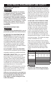
ELECTRICAL REQUIREMENT AND SAFETY POWER SUPPLY AND MOTOR SPECIFICATIONS Use a separate electrical circuit for your tool. This circuit must not be less than #16 wire and should be protected with a 10 Amp time lag fuse. Before connecting the motor to the power line, make sure the switch is in the off position and the electric current is rated the same as the current stamped on the motor nameplate. Running at a lower voltage will damage the motor.
This tool is intended for use on a circuit that has a receptacle like the one illustrated in Fig. 1. Fig. 1 shows a three-pronged electrical plug and receptacle that has a grounding conductor. If a properly grounded receptacle is not available, an adapter (Fig. 2) can be used to temporarily connect this plug to a two-contact grounded receptacle. The adapter (Fig. 2) has a rigid lug extending from it that MUST be connected to a permanent earth ground, such as a properly grounded receptacle box.
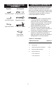
TOOLS NEEDED FOR ASSEMBLY Supplied 2 mm hex wrench CARTON CONTENTS UNPACKING AND CHECKING CONTENTS Carefully unpack the band saw and all its parts, and compare against the list below and the illustration on the next page. With the help of an assistant place the saw on a secure surface and examine it carefully. Not Supplied Phillips screwdriver ! WARNING To avoid injury from unexpected starting or electrical shock, do not plug the power cord into a source of power during unpacking and assembly.
UNPACKING YOUR BAND SAW B A C D E 10
KNOW YOUR BAND SAW Upper wheel cover Blade tension knob Upper blade wheel Upper cover lock knob Blade guard Blade guide height adjustment knob Upper blade guide ON/OFF switch Miter gauge Table aligning bolt Lower blade guide Wheel brush Lower cover lock knob Lower blade wheel Lower wheel cover Blade tracking knob Upper guide lock knob Blade Power cord Table Table tilt scale Table tilt adjustment knob Motor Sawdust port Table lock handle 11
GLOSSARY OF TERMS BAND SAW TERMS LEADING EDGE — The front edge of the workpiece pushed into the cutting tool first. BLADE GUIDES — Support the blade and keep it from twisting during operation. Blade guides must be adjusted when blade is changed or replaced. MITER CUT — An angle cut made across the width of a workpiece. RESAW — A cutting operation to reduce the thickness of the workpiece to make thinner workpiece. UPPER GUIDE LOCK KNOB — locks the upper slide.
ASSEMBLY AND ADJUSTMENTS Estimated Assembly Time: 50 - 60 minutes. 6. Replace the table aligning nut (2) back intot the place and tighten with the table aligning bolt (1). ! WARNING For your safety, never connect plug to power source receptacle until all assembly and adjustment steps are complete, and you have read and understood the safety instructions. Fig. C 7 INSTALLING THE BAND SAW TABLE (FIG. A, B, C) 1.
Installing 1. Make sure the blade tension knob (1) is turned counterclockwise enough to get blade over pulleys. 2. Remove old blade as explained in “Removing” section. 3. Guide the new blade (8) through the slot (12) of the left side blade guard. Make sure the blade teeth are pointing forward and down. NOTE: To avoid lifting the workpiece, the blade teeth must point downward toward the table. 4. Place the blade (8) on the upper and lower wheels (11). 5.
INSTALLING A NEW BELT (FIG. F) 1. Open the lower wheel cover. 2. Loosen the blade tension by turning the blade tension knob. 3. Remove the blade from the lower wheel assembly. 4. Using a snap ring pliers, remove snap ring (1) that secures lower wheel (2) to shaft (3) and flange (4) on the lower blade wheel. 5. Loosen the belt tension by loosen the hex screw on the motor with a 6 mm hex wrench. See "DRIVE BELT TENSION" on page 18. 6. Slide lower wheel assembly off the shaft (3) which will dislodge the belt.
BLADE TENSION (FIG. H) The blade must be slightly tensioned before adjusting blade tracking. Make sure blade guides and bearings do not interfere with blade. ! WARNING ● To avoid injury, turn the switch OFF and disconnect the saw from the power source before making any adjustments. NEVER make tension adjustments with the machine running. ● Blade tension was set at the factory. When adjustment is needed please follow the procedure below. 1. Open upper and lower doors.
UPPER BLADE GUIDES AND BLADE SUPPORT BEARING (FIG. J, K) 6. Loosen the side hex screw (4) by turning counterclockwise with a 4 mm hex wrench supplied. 7. Move the upper blade guide brackets (5) in or out until the guide pins (2) are just behind the blade teeth. 8. Tighten the side hex screw (4). ! WARNING The blade guard has been removed for clarity of illustration. To avoid injury, never operate the band saw without all guards in place and in working order. Fig.
Blade guides 1. Loosen two front hex socket screws (1) with a hex wrench. 2. Move the guide pins (2) as close to the sides of the blade (3) as possible without pinching it. 3. Using the feeler gauge, measure the spaces between the guide pins and the blade. Adjust to 0.002 in. (0.05 mm). 4. Tighten two front hex socket screws (1). 8. Tighten the support bearing hex screw (6). 9. The back edge of the blade (3) should be positioned 1/16 in. (1.6 mm) to 1/8 in. (3.
OPERATION BASIC SAW OPERATIONS Do not force the workpiece against the blade. Light contact permits easier cutting and prevents unwanted friction and heating of the blade. “ON/OFF” SWITCH (FIG. P) The switch with safety key is intended to prevent unauthorized use of the band saw. 1. To turn the band saw ON, insert the yellow safety key (1) into the key slot in the center of the switch (2). 2. Push the key firmly into the slot, then push switch (2) to the ON position to start the band saw. 3.
Fig. Q FREE WARNING LABEL REPLACEMENT: If your warning labels become illegible or are missing, call 1-888-609-9779 for a free replacement. (12.7 mm) (25.4 mm) 1/2 in. D 1 in. D 1/8 in. 3/16 in. (3.2 mm) (4.8 mm) (38.1 mm) (50.8 mm) 1-1/2 in. D 2 in. D 1/4 in. (6.4 mm) Minimum (63.5 mm) 2-1/2 in. D Circle Diameter 3/8 in. (9.5 mm) 1/2 in. (12.7 mm) Blade Width BLADE SELECTION (FIG. R) ! CAUTION Blade teeth are sharp. Use care when handling a saw blade.
MAINTENANCE GENERAL MAINTENANCE MOTOR Frequently blow or vacuum out any sawdust from the motor. Follow lubrication instruction on the motor label. ! WARNING For your own safety, turn the switch OFF and remove the plug from power source before maintaining, cleaning, adjusting or lubricating your band saw. ! WARNING To avoid electrocution or fire, immediately replace a worn, cut or damaged power cord.
TROUBLESHOOTING GUIDE ! WARNING To avoid injury from an accidental start, turn the switch OFF and always remove the plug from the power source before making any adjustments. REPLACEMENT PARTS Use only identical replacement parts. For a parts list or to order parts, visit our service website at www.portercable.com. You can also order parts from your nearest Porter-Cable Factory Service Center or Porter-Cable Authorized Warranty Service Center. Or, you can call our Customer Care Center at (888) 609-9779.
MOTOR PROBLEM Noisy operation. PROBLEM CAUSE 1. Incorrect belt tension. SUGGESTED CORRECTIVE ACTION 1. Adjust tension. See ASSEMBLY AND ADJUSTMENTS section - "DRIVE BELT TENSION." 2. Readjust and tighten motor pulley set screw. 3. Readjust and tighten pulley cover mounting screws. 2. Loose motor pulley. 3. Loose pulley cover. Motor will not start. 1. Not plugged into power outlet. 1. Plug it into the power outlet. 2. Switch and key not in ON 2. Insert key and turn the switch ON. position. 3.
ACCESSORIES AND ATTACHMENTS ACCESSORIES ! WARNING ! WARNING Since accessories, other than those offered by Porter-Cable, have not been tested with this product, use of such accessories with this tool could be hazardous. To reduce the risk of injury, only Porter-Cable recommended accessories should be used with this product. Do not use any accessory unless you have completely read the Instruction Manual for that accessory.
PARTS LIST 9 IN.
X7BZ X7BY X7C0 X7F1 X7BP X7C1 X7F7 X7F6 X7F5 X7F4 X7BW X7F6 X7F4 X7F3 2 X7F5 X7EZ X7EY2 X7C2 X7BN X7E4 X7F0 X7EP X7EQ X7CC X7EV X7BJ X7CE X7CH X7CD X4CC X7BL X7HV 3 X7HU 3 X7EY2 X7EX 2 X7EL X7ES X7ET X7C9 X7F3 2 X7EG X7EN 2 X7DZ X7E2 2 X7DY X7EV X7EX 2 X7BK X7EZ X7BM X7EL X7E1 X7E0 X7E7 X7E3 X7E2 X7E8 X7BQ X7HW 2 X7E5 2 X7BR X7EH 2 X7F2 X7EA X7EB X7EC 2 X7ED X7EE X7BS X7E9 X7HW 2 X7CG X7CF X7DW X7DS X7EJ X7E5 2 X7CA X7EU X7EK X7DN X7EM
NOTES 27
WARRANTY THREE YEAR LIMITED WARRANTY PORTER-CABLE will repair, without charge, any defects due to faulty materials or workmanship for three years from the date of purchase. This warranty does not cover part failure due to normal wear or tool abuse. For further detail of warranty coverage and warranty repair information, visit www.portercable.com or call (888) 609-9779. This warranty does not apply to accessories or damage caused where repairs have been made or attempted by others.