4" RESTORER Model # PXRA2676 Owner’s Manual Rating: Amperes: Speed: Sanding roller size: Weight: PRODUCT SPECIFICATIONS 120 V, 60 Hz AC 3.5 A 1,000 – 3,200 RPM (no load) 2 13/16" (72mm) diameter 4" (100mm) wide 4 lb. 8 oz. (2.
TABLE OF CONTENTS Product specifications ………….………………………………………………………………... Table of contents …………………………………………………………………….................. General safety warnings ………………………………………………………………………… Eye, ear & lung protection ………………………………………………………………………. Electrical safety …………………………………………………………………………………... Power tool safety …………………………………………………………………….................. General safety rules ……………………………………………………………………………... Work area ………………………………………………………………….……………………...
GENERAL SAFETY WARNINGS ! WARNING: Before using this tool or any of its accessories, read this manual and follow all Safety Rules and Operating Instructions. The important precautions, safeguards and instructions appearing in this manual are not meant to cover all possible situations. It must be understood that common sense and caution are factors which cannot be built into the product.
GENERAL SAFETY WARNINGS WEAR A DUST MASK THAT IS DESIGNED TO BE USED WHEN OPERATING A POWER TOOL IN A DUSTY ENVIRONMENT. ! WARNING: Dust that is created by power sanding, sawing, grinding, drilling, and other construction activities may contain chemicals that are known to cause cancer, birth defects, or other genetic abnormalities.
POWER TOOL SAFETY ! WARNING: Read all safety warnings and instructions. Failure to follow the warnings and instructions may result in electric shock, fire and/or serious injury. When operating a power tool outdoors, use an extension cord suitable for outdoor use. Use of a cord suitable for outdoor use reduces the risk of electric shock. Save all warnings and instructions for future reference.
POWER TOOL SAFETY Personal safety – cont’d Use the power tool, accessories and tool bits etc. in accordance with these instructions, taking into account the working conditions and the work to be performed. Use of the power tool for operations different from those intended could result in a hazardous situation. If devices are provided for the connection of dust extraction and collection facilities, ensure these are connected and properly used. Use of dust collection can reduce dustrelated hazards.
SPECIFIC SAFETY RULES ! WARNING: Know your Restorer. Do not plug in the Restorer until you have read and understand this Instruction Manual. Learn the tool’s applications and limitations, as well as the specific potential hazards related to this tool. Following this rule will reduce the risk of electric shock, fire, or serious injury. ! WARNING: Always use safety goggles and a dust mask when using compressed air to remove sanding dust from the tool.
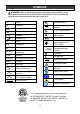
GUIDELINES FOR EXTENSION CORDS Make sure your extension cord is the proper size. When using an extension cord, be sure to use one heavy enough to carry the current the tool will draw. An undersized cord will cause a drop in line voltage resulting in loss of power and overheating. The table at right shows the correct size to use according to cord length and nameplate ampere rating. If in doubt, use the next heavier gauge. The smaller the gauge number the heavier the cord.
SYMBOLS ! WARNING: Some of the following symbols may appear on the Restorer. Study these symbols and learn their meaning. Proper interpretation of these symbols will allow for more efficient and safer operation of this tool. V A Hz W kW L kg H N/cm2 Pa OPM Min S or a.c.
KNOW YOUR RESTORER Front handle Variable speed control Lock-on button ON/OFF trigger switch Main handle Dust port Air vents Roller end cover hasp Roller end cover clamp Roller Coarse sanding sleeve (2) Roller end cover Medium sanding sleeve (2) 10 Fine sanding sleeve (2)
ASSEMBLY AND OPERATING CHANGING SANDING SLEEVE ON ROLLER 6 ! WARNING: Remove the plug from the power source before installing or removing a sanding roller. 1. Lift the two roller end cover hasps (1) away from the main housing (2) (Fig. 1). 4 1 2 Fig. 3 1 6. Slide the roller onto the roller shaft (Fig. 4). NOTE: The roller can only be installed one way. When properly installed, the directional arrow (7) on the end of the roller will be visible. 3 Fig. 1 2.
ASSEMBLY AND OPERATING 4. VARIABLE SPEED CONTROL – cont’d To release the lock-on button to turn the tool OFF, squeeze and then release the trigger. The trigger switch will then turn OFF. 1 2 1 Fig. 5 Fig. 7 ON/OFF TRIGGER SWITCH ! WARNING: Be sure the lock button is not depressed by cycling the ON/OFF switch several times or by depressing and releasing the switch several times before plugging in your restorer. Damage to your tool or personal injury may result.
ASSEMBLY AND OPERATING To begin sanding, install the appropriate sanding sleeve, set the tool speed and squeeze the trigger switch to turn the tool ON. NOTE: The sanding sleeve should NOT be in contact with the workpiece until it has reached its operating speed. SANDING This tool can be used to sand rough material or to remove paint, varnish or other finishes. ! WARNING: Always use safety glasses, dust mask and hearing protection when operating this tool.
ASSEMBLY AND OPERATING SANDING – cont’d CLEANING THE TOOL Always keep the tool "moving" when the sanding sleeve is in contact with the workpiece. This is particularly important when sanding wood or other soft materials. Failure to keep the tool "moving" will result in gouges in the workpiece. It is important to keep the tool as clean as possible to reduce the risk of fire and to produce the best possible sanding results.
MAINTENANCE GENERAL It has been found that electric tools are subjected to accelerated wear and possible premature failure when they are used on fiberglass boats and automotive parts, wallboard, spackling compounds or plaster. The chips and grindings from these materials are highly abrasive to electric tool parts such as bearings, brushes, commutators, etc. Consequently, it is not recommended that this tool be used for extended work on any fiberglass material, wallboard, spackling compounds or plaster.
EXPLODED VIEW 7 5 6 3 4 2 1 8 9 10 11 39 12 38 13 14 15 37 36 35 34 33 32 31 30 16 17 29 18 19 20 28 21 22 23 24 25 26 27 16
PARTS LIST ! WARNING: When servicing, use only original equipment replacement parts. The use of any other parts may create a safety hazard or cause damage to the Restorer. ! WARNING: To assure SAFETY and RELIABILITY of repairs, maintenance and accessories, the use of any accessory not recommended for use with this tool could be hazardous. Recommended accessories for use with your tool are available from your local dealer or authorized service center.
PARTS LIST Key # 34 35 36 37 38 39 Part # 4030010008 1230010146 2030070053 3160010072 4030010106 1250010002 Part Name Tapping screw ST2.5X8 Carbon brush Brush holder Motor cover Tapping screw ST3.9X19 Terminal block Quantity 4 2 2 1 3 1 THREE YEAR LIMITED WARRANTY PORTER-CABLE will repair, without charge, any defects due to faulty materials or workmanship for three years from the date of purchase. This warranty does not cover part failure due to normal wear or tool abuse.