
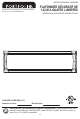
Installation Guide


With power disconnected to your electrical box, remove the old fixture. If your old fixture is attached to
an electrical box having more than two (2) wire leads, it is recommended you use tape and markings
to keep track of which wires were attached to each other.
PREPARATION
ASSEMBLY INSTRUCTIONS
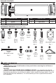
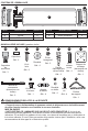
Before beginning assembly of product, make sure all parts are present. Compare parts with
package contents list and diagram above. If any part is missing or damaged, do not attempt to
assemble the product. Contact customer service for replacement parts.
Estimated Assembly Time: 45 minutes
Tools Required for Assembly (not included): drill, 1/16” drill bit, phillips head screwdriver, flathead
screwdriver, safety glasses, electrical tape, pliers, wire cutters, wire strippers, step ladder.
HH
GG
GG
GG
HH
1
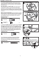
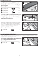
2. Place the fixture pan over the two machine screws protruding
from mounting plate (HH), and position it into the desired
mounting location. Locate the round holes at each end of the
fixture pan and mark their center location onto the ceiling.
Remove the fixture pan and drill a 1/16 in. pilot hole into the
marked locations. If the fixture is being mounted to drywall,
insert the drywall anchors (FF) into the holes and screw them
into place so they are flush with the surface of the drywall
(Fig. 2). NOTE: When drilling the pilot hole if contact is made
with wood DO NOT install the drywall anchor.
Hardware Used
Drywall
Anchor
FF
x 2
1. Screw two of the short machine screws (GG) into the
threaded holes on the mounting plate (HH) on the side NOT
labeled GND. Depending on the type of electrical box, you may
need to modify the mounting plate (HH) by removing knockouts
that correspond to the mounting screws on your electrical box.
Pull the supply wires through the center hole of the mounting
plate (HH). Attach the mounting plate (HH) to the electrical box,
on the side labeled GND, using screws removed from the
electrical box or two of the machine screws (GG)
provided (Fig. 1).
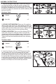
3. Pull the fixture wires through the hole in the center of the
fixture pan (A) to the backside of the fixture. Using the support
chain (NN), connect one end to the back of the fixture pan near
the center in the specially designed slots and hook the other
end to the mounting plate (HH) (Fig. 3). This will allow for a
hands free support for wiring.
Hardware Used
x 4
Short Machine
Screw
GG
Hardware Used
x 1
Support Chain
NN
Mounting
Plate
x 1
HH
GND
GND
GND
2
A
FF
3
NN
NN
A
3