
Installation Guide

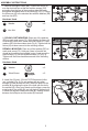


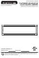

6. Locate the square openings at the ends of the fixture
pan (A). Insert the carriage bolts (II) through the square
openings from the backside of the fixture pan (Fig. 6).
The carriage bolt’s threaded ends will be closet to the floor.
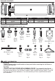
Hardware Used
x 2Carriage Bolt
II
ASSEMBLY INSTRUCTIONS
AA
Wire Nut
Hardware Used
x 2
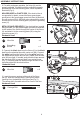
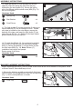
5. Connect the black lead from the fixture (A) to the black
lead from the electrical box with a wire nut (AA). Connect
the white lead from the fixture (A) to the white lead from
the electrical box with a wire nut (AA). Make sure the wire
nuts (AA) are tight. If needed, wrap electrical tape around
the wire nuts (AA) to prevent them from coming loose
(Fig. 5). Carefully push the wires through the hole of the
mounting plate into the electrical box.
Wire Nut x 1
AA
Grounding
Screw
x 1
JJ
Hardware Used
4.
For safety, and proper operation, the fixture (A) must be
properly grounded. If unfamiliar with the methods for properly
grounding the fixture and mounting plate, consult a qualified
electrician (Fig. 4).
NON-GROUNDED or PLASTIC BOX: If the electrical box is
non-grounded, or plastic, connect the fixture green/copper
ground wire to the green/copper ground wire from the electrical
box with a wire nut (AA), AND then make a loop with the ground
wire and secure it to the mounting plate (HH) with the grounding
screw (JJ).
METAL BOX AND GROUNDED:
If the electrical box is metal
and grounded, run the green/copper ground wire attached
to the inside of the fixture through the center of the fixture
(A) and attach it to the mounting plate (HH) using the
grounding screw (JJ).
HH
AA
JJ
4
JJ
HH
5
AA
AA
AA
4
A
6
II
A
A
II