
Installation Guide


2
2. To mount the fixture (A), the wire compartment cover (D) must
be removed to expose the mounting slots. One end has a fastener
(HH) that needs to be rotated 1/4 of a turn turn in either direction.
Once that end is loosened, pivot the end up until the catch-tab is
released from its securing slot. NOTE: Do not pivot the wire
compartment cover (D) past 90° or the tab and slot may be
damaged.
Place fixture (A) up to the mounting surface and mark
the positions of the narrow end of the keyslot holes on
the mounting surface with a pencil. The 2 screw hole
locations must be exact for the fixture (A) to mount
properly.
With power disconnected to your electrical box, remove the old fixture. If your old fixture is attached to
an electrical box having more than two (2) wire leads, it is recommended you use tape and markings
to keep track of which wires were attached to each other.
PREPARATION
ASSEMBLY INSTRUCTIONS
Before beginning assembly of product, make sure all parts are present. Compare parts with
package contents list and diagram above. If any part is missing or damaged, do not attempt to
assemble the product. Contact customer service for replacement parts.
Estimated Assembly Time: 45 minutes
Tools Required for Assembly (not included): Phillips head screwdriver, flathead screwdriver,
safety glasses, electrical tape, pliers, wire cutters, wire strippers, step ladder.
A
A
B
B
B
D
D
HH
FF
EE
EE
Mounting
Plate
FF
x 2
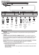
Hardware Used
Short Machine
Screw
x 2
EE
1. If the mounting plate (FF) has more than 2 threaded holes,
measure the center-to-center distance of the holes to make
sure it matches the hole openings in the fixture pan (A).
Remove the appropriate knockouts from the mounting plate
(FF). Pull the supply wires (and ground wire, if present)
through the center opening of the mounting plate (FF) and use
the short machine screws (EE) to attach the mounting plate
(FF) to the electrical box. Make sure both short machine
screws (EE) are securely tightened down.
Hardware Used
Fastener x 1
HH
1
3