
Installation Guide


3.
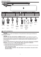
Remove the round and “T” knockouts in the center of
the fixture (A).
ASSEMBLY INSTRUCTIONS
A
A
3
4. WALL STUD MOUNTING: For mounting over the wall
stud, drill two small pilot holes for the wood screws (CC).
While holding your fixture pan (A) in line with the pilot
holes, screw the wood screws (CC) into the wooden
studs. Tighten until the fixture pan (A) has been secured to
the mounting surface.
DRYWALL MOUNTING: For mounting into drywall, drill
3/16 in. holes for the wood screws (CC). Insert the drywall
anchors (DD) into the proper holes and screw them into
place so they are flush with the surface of your drywall.
While holding your fixture pan (A) in line with the drywall
anchors (DD), screw both wood screws (CC) into the
drywall anchors (DD). Tighten until the fixture
pan (A) has been secured to the mounting surface.
Hardware Used
Wood
Screw
x 2
CC
Drywall
Anchor
x 2
DD
4
CC
Wire Nut x 1
AA
Grounding
Screw
x 1
GG
Hardware Used
CC
DD
5.
For safety, and proper operation, the fixture (A) must be
properly grounded. If unfamiliar with the methods for properly
grounding the fixture and mounting bracket, consult a qualified
electrician.
NON-GROUNDED or PLASTIC BOX: If the electrical box is
non-grounded, or plastic, connect the fixture green/copper
ground wire to the green/copper ground wire from the electrical
box with a wire nut (AA), AND then make a loop with the ground
wire and secure it to the mounting bracket (FF) with the
grounding screw (GG).
METAL BOX AND GROUNDED:
If the electrical box is metal
and grounded, run the green/copper ground wire attached
to the inside of the fixture through the center of the fixture
(A) and attach it to the mounting plate (FF) using the
grounding screw (GG).
GG
FF
FF
AA
GG
5
4