
Owner's manual

Top Piece Installation
(8040 and 8050 Models)
Materials:
• Part C
NOTE: Leave pre-installed Corner Pads in place.
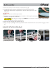
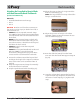
1. Remove the two Allen Head Screws from the
Top Piece (Part C) and keep for use at a later step.
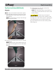
2. Place each Top Piece section into the Metal
Retainers on the head of the A-Frame Legs (Fig. 16).
NOTE: For one-person set-up, insert the Top
Piece one end at a time.
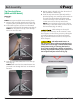
3. Push the Silver Metal Detent Pin into the top
hole (Fig. 17).
NOTE: Make sure the Silver Metal Detent Pin
protrudes out through the hole on the Metal
Retainer.
Bottom Hole
Top Hole
Corner Pads
Fig. 16
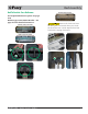
4. Repeat Steps 1 through 3 for the other side of
the assembled A-Frame Legs.
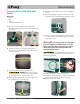
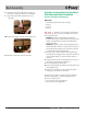
5. Slide the Top Center Piece (Part B1) with the
provided springs over each Top Piece and then
re-install. Do NOT tighten the Allen Head
Screws from Step 1. Slots should be oriented
on the same side as the Top Piece holes
NOTE: The Top Center Piece must be able to
slide freely so that the frame can move as the
bed articulates (Figs. 18 and 19).
The bed may not always fit
through some doorways. In this situation, lower
the top piece to the lowest position, pushing the
Silver Metal Detent Pin into the bottom hole
(Fig. 16), and then return it back to the top hole
after transport.
Bottom Hole
Top Hole
Corner Pads
Fig. 17
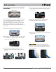
The Allen Head Screws on
the top center piece of the Posey Bed must be
secure, but loose enough so the A-Frame slides
freely when raising or lowering the head or
foot of the hospital bed. A failure to heed this
warning may interfere with proper operation of
the hospital bed (See red arrows fig. 18).
Fig. 19
B1
C
12 Posey Bed - 8040, 8050, 8060
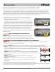
Bed Assembly
TOP PIECE FULLY ASSEMBLED
Fig. 18