SL & Jiva EL EL Jiva SL (TP-5700/5800) SERIES USER’S MANUAL WORK STATION Rev.
SOME IMPORTANT NOTES FCC NOTES This equipment generates, uses, and can radiate radio frequency energy and, if not installed and used in accordance with the instructions manual, may cause interference to radio communications. It has been tested and found to comply with limits for a Class A digital device pursuant to subpart J of Part 15 of FCC Rules, which are designed to provide reasonable protection against interference when operated in a commercial environment.
TABLE OF CONTENTS BRIEF INTRODUCTION . . . . . . . . . . . . . . . . . . . . . . . . . . . . . . . . . . 1 - 1 THE USER’S MANUAL . . . . . . . . . . . . . . . . . . . . . . . . . . . . . . . . 1 THE PRODUCT . . . . . . . . . . . . . . . . . . . . . . . . . . . . . . . . . . . . . . . 1 Overview . . . . . . . . . . . . . . . . . . . . . . . . . . . . . . . . . . . . . . . 1 Configuration . . . . . . . . . . . . . . . . . . . . . . . . . . . . . . . . . . . . 1 Available Models . . . . . . . . . . . . . . . .
WALL MOUNTING . . . . . . . . . . . . . . . . . . . . . . . . . . . . . . . . . . . . 3 LOCATION FOR INSTALLATION . . . . . . . . . . . . . . . . . . . . . . . 3 OPERATING SYSTEM RECOVERY . . . . . . . . . . . . . . . . . . . . . 3 - 6 6 7 USING THE TOUCH POS . . . . . . . . . . . . . . . . . . . . . . . . . . . . . . . . 4 - 1 APPLICATION ENVIRONMENT . . . . . . . . . . . . . . . . . . . . . . . . . 4 Ventilation . . . . . . . . . . . . . . . . . . . . . . . . . . . . . . . . . . . . . .
BRIEF INTRODUCTION THE USER’S MANUAL The purpose of this manual is to guide the user in the initial installation and general use of the Posiflex fully integrated compact touch interface workstation. Jiva SL & Jiva EL (TP5700/5800) series is a product group of fully integrated PC based Point-Of-Sale systems. However, this manual does not intend to explain any application program that may be supplied with the systems.
STANDARD FEATURES a) CPU: Celeron compatible 400 MHz up b) HDD: available for fat client models c) Support Win98, Win2000 in fat client models, and WinCE, Win XP embedded & Linux environment throughout whole series d) Support thin client architecture either boot from WinCE in CF card or Linux LAN boot e) Fanless design (for thin client models) to reduce dust/grease accumulation f) High quality 12.
n) o) p) q) r) s) t) 12. one CR port for control over 2 cash drawers max. 13. audio ports (1 Microphone input and 1 audio line output) Touch control functions: left/right button, double click, drag & draw High resolution touch sensor: 1024 x 1024 Dual display support VGA memory size shared from system memory (8 – 64 MB) Support high performance DDR266 DRAM with maximum memory size 1GB in two modules Integrated structure for optional security devices (incl.
Jiva SL & Jiva EL (TP5700/5800) USER’S MANUAL 1 - 4
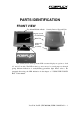
PARTS IDENTIFICATION FRONT VIEW Top Mount PD302 on Back Security Devices Upgrade Unit Display Screen + Touch Panel Main Unit Adjustable Stand Assembly The security device and top mount LCD customer display are options to both 12” and 15” models. The LED in the logo area serves for several purposes through giving different indication of steady/flashing green/blue light. Please refer to the paragraph discussing the LED indication in the chapter of “USING THE TOUCH POS” of this manual.
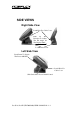
SIDE VIEWS Right Side View Latch Hole For Cable Cover Push In This Direction To Adjust The Tilt Angle Of The Display Panel Lock/Release Lever Left Side View Push Down To Switch The Power ON/OFF Latch Hole For Cable Cover Slide Switch For Power On/Off Control Jiva SL & Jiva EL (TP5700/5800) USER’S MANUAL 2 - 2
REAR VIEW Lock/Release Button To Detach The Main Unit Optional Security Devices Lock/Release Lever Cable Exit REAR VIEW OF MAIN UNIT Service Window Matching Pegs Cable Exit Cable Cover Removal Hollow Of Cable Cover Jiva SL & Jiva EL (TP5700/5800) USER’S MANUAL 2 - 3
ADJUSTABLE STAND ASSEMBLY Matching Holes Stand Base Lock/Release Lever BOTTOM OF STAND ASSEMBLY Base UPS Battery Cover Lock/Release Button For Main Unit Cable Passage Cover Cable Exit Stand Jiva SL & Jiva EL (TP5700/5800) USER’S MANUAL 2 - 4
CONNECTORS Turn Counterclockwise Then Take Out The Latch Key Pull The Cable Cover Out In This Direction Locations of I/O Ports in original revision: ★CF Card Port ★CDROM Port PS2 KB LPT Port PS2 Mouse LED Connector COM2 Port Power Input Jack CR Port COM1 Port Audio Out Port LAN Port Audio (Mic) Input Port USB1 Port COM3 Port UPS Battery Connector USB0 Port External VGA Connector ★COM4 Port ★ CF Card Port is available in thin client models only.
Jiva SL & Jiva EL (TP5700/5800) USER’S MANUAL 2 - 6
INSTALLATION GUIDES CAUTION: Before any installation or cable connection to the set, please always make certain that the system is turned off and the external power source to the set is removed to prevent electric hazard! Never touch any metal pin in the connectors or circuits to avoid high voltage hazard or electrostatic discharge damage unless the operator is well grounded.
PREPARING STAND ASSEMBLY Take the adjustable stand assembly and turn it up side down to show the bottom of the base. 2 Sets of 4 Matching Holes Screws Cable Passage Cover Adjustable Stand Now, unscrew the 2 screws on the cable passage cover and take the cable Lock/Release passage cover away to show the cable Lever passage.
INSTALLING UPS BATTERY UPS Battery Removed Battery Cover Place the optional UPS battery in the battery compartment (shown top left). Screw on the battery cover and route the battery cable through the base. Please enable the UPS features in the software settings before use. ROUTING THE CABLES Place all the cables required for connections to the Jiva SL & Jiva EL (TP5700/5800) series except those for special application purposes into the cable passage.
Service Window Push Open To The Right 4 Matching Pegs This battery socket accepts a 3 V button cell Lithium battery (CR2032) required to support the system real time clock. The jumpers in this window are designated for COM port power supply function. Please consult your dealer for technical support on setup of these jumpers. A new Lithium battery can support the system RTC for about 3 years.
OPENING CABLE COVER Insert the tip of the latchkey into a latch hole on one side near bottom of the main unit. Turn this key counterclockwise to the end. Do the same on the opposite side. Be sure to take the key out of the hole. Turn Counterclockwise Then Take Out The Latchkey Then push the lock/release lever on the base backward to adjust the stand to the most horizontal position for ease of operation. Open the cable cover by pulling at the removal hollow.
both sides to secure the cable cover on the main unit. Adjust the tilt angle of the main unit for best viewing effect in the application. CAUTION: On doing any insertion or extraction of any connector, please always hold the connector head itself instead of pulling on the cable wire. Failure to do this could damage the cable and jack that is considered as an artificial destruction and is not covered by the warranty. WALL MOUNTING The major part in the wall mounting kit is a bracket as shown in the picture.
consideration. If the main unit is tilted to near vertical position, the total height can be either 360 mm or 380 mm depending on the position adjusted. When the main unit is tilted to near horizontal position, the total height required is 275 mm. OPERATING SYSTEM RECOVERY For TP5712 and TP5715 models, if not using a remote boot operating system, the operating system exists in the Compact Flash Card. Therefore, once the Compact Flash is damaged for any reason, the thin client may fail to boot.
Jiva SL & Jiva EL (TP5700/5800) USER’S MANUAL 3 - 8
USING THE TOUCH POS APPLICATION ENVIRONMENT It is very important that you check the following operational guidelines: Ventilation This terminal must NOT be operated in an environment with restricted ventilation. The installation should be such that there is at least 25mm air clearance around any top or side ventilation holes. The installation must also be such that there is a free flow of air around the unit at ALL times.
There is an LED in the logo area or under the printed logo for system revision that serves for several purposes.
Switch Manager” in “Posiflex Tools” in the Program Files helps managing these functions. Software Support The Jiva series provides a software power off command for application program maneuvers. The Jiva also provides a specific means for the software to detect if the system is working on external or UPS battery power. Due to this feature, compatible software applications have the ability to change operating conditions when running on standard/backup power.
through pin 9 after proper jumper setting change. All 4 ports are standard RS232 serial ports. When a serial Modem is to be used in Jiva SL & Jiva EL series, it is most recommended to use COM2 or COM3 port for this purpose. In this way any hardware resource conflict is eliminated and the MODEM ring up function can be supported. For RS232 touch interface models, COM4 is occupied and covered. Please never try to open the cover. Otherwise the product warranty is voided.
controller, touching any point on the screen surface after touching the right-click sticky button results as a click on the right button of the mouse at that point. However, the right button function is applicable only under the WIN 98 environment. TOUCH TERMINAL MANAGER The touch panel control parameters are already well calibrated in the factory prior to delivery. In principal, the touch panel requires no further calibration once properly set.
If, for any reason, the user wants to remove the driver for the RS232 touch controller, please select “Monitor Mouse for Windows 95” in the program list for removal.