
Cash Register User Manual


ANNEX
ANNEX: WALL MOUNT APPLICATION
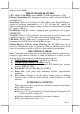
The wall mount option kit contains 2 pcs of plastic cotters, 2 pcs of self-tapping screws and 1 pc of metal wall
mount bracket as drawn in template below. Select a flat surface on wall of adequate strength and with proper ventilation
and space condition. Apply the below printed drilling template on the wall surface. Drill 2 holes in horizontal layout as
marked as dashed crosses in the template that is 5.3” or 135 mm wide (center to center). Hole
diameter should be 1/4” or 6.35 mm each. Hole depth should be at least 1 and 3/8” or 35 mm.
Please then insert one plastic cotter into each hole leaving the flat end with hole of the plastic
cotter at the outside opening of the hole. Use a hammer to tap the plastic cotter in gently if
necessary. Please then screw the bracket into the plastic cotters with the guide grooves on top
side.
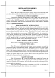
Now please check the bottom of KV-2000 that there are 2 metal studs on the power
switch side of the bottom as in the left drawing. Slide the KV-2000 from above the bracket with
the studs well caught in the guide grooves. Seat the KV-2000 to the left when it arrives the
bottom of the grooves. Turn the antenna to appropriate direction if the Wireless LAN option is
installed.
Please then do the connection to power adaptor and other required cables for operation.
Guide Grooves
Studs