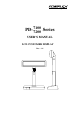
PD- 7100 Series 7200 USER’S MANUAL LCD CUSTOMER DISPLAY Rev.
SOME IMPORTANT NOTES FCC NOTICE This equipment generates, uses, and can radiate radio frequency energy and, if not installed and used in accordance with the instructions manual, may cause interference to radio communications. It has been tested and found to comply with limits for a Class A digital device pursuant to subpart J of Part 15 of FCC Rules, which are designed to provide reasonable protection against interference when operated in a commercial environment.
TABLE OF CONTENTS GENERAL DESCRIPTION · · · · · · · · · · · · · · · · · · · · · 1 Introduction · · · · · · · · · · · · · · · · · · · · · · · · · 1 Application · · · · · · · · · · · · · · · · · · · · · · · · · · 1 Special Features · · · · · · · · · · · · · · · · · · · · · · · 1 Description · · · · · · · · · · · · · · · · · · · · · · · · · · 1 Model Numbers · · · · · · · · · · · · · · · · · · · · · · · 1 ACCESSORIES · · · · · · · · · · · · · · · · · · · · · INSTALLATION · · · · · · · · · · · · · · · · · · ·
Normal Operation Ratings · · · · · · · · · · · · · · · · · · 5 - 1 OPTICAL CHARACTERISTICS · · · · · · · · · 5 - 1 - 1 - 2 Character Format · · · · · · · · · · · · · · · · · · · · · · 5 Fundamental Specification · · · · · · · · · · · · · · · · · · 5 ENVIRONMENTAL CHARACTERISTICS ii ·5 - 2
I. GENERAL DESCRIPTION A. Introduction This documentation describes the features and requirements of the product series of PD-7100 / 7200, a Liquid Crystal Display which is a wide customer display. It displays alphanumerical characters in 2 lines of 20 large sized characters and is able to display in 4 lines of 26 alphanumerical characters per line to show more information at a time.
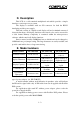
D. Description This LCD is a self-contained multiplexed unit which provides a simple interface to a microprocessor system. The display is available with one I/O connector for both the RS232 interfacing and the power supply. This unit consists of a liquid crystal display cell and a minimal amount of electronic hardware. All display characters and control codes can be accessed in a 8-bit format. Primary complexity is contained within the microprocessor software, which controls all display functions.
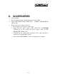
II. • • • • ACCESSORIES User’s manual Pass through terminator (already plugged at bottom of PD) Signal cable 20863137210 (CCBLA-372) – a DB-9F to DB-9M RS232 cable 1.8 M Power source (one of the four below): Power adaptor specified per country type Power kit incl.
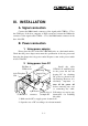
III. INSTALLATION A. Signal connection Connect the DB9 female connector of the signal cable CCBLA - 372 to the COM port of the host computer or POS system and connect the DB9 male connector of the signal cable CCBLA – 372 to the DB9 female connector in the base of the PD. B. Power connection 1. Using power adaptor Please place the base of the PD-7100/7200 series on a horizontal surface.
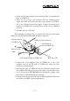
3. Select one I/O plate position on rear window of PC to install the I/O plate of CCBLA-141. 4. Select one set of large 4 pin connector from the switching power supply unit of PC and connect the male 4 pin connector of CCBLA141 to the connector from power supply. Connect the female 4 pin connector of CCBLA-141 to the I/O device of PC such as a HDD if necessary. 5. Assemble the case of PC back. Then referring to drawing below to complete the basic power and signal cabling.
3. Using power from POS system This super convenient power supply method applies only when connected to a Posiflex POS system after proper setting for power in COM port. The power connection is already done when the signal connection is completed. 4.
Please reserve the COM port terminator in a safe place in case the non-passthrough operation would be required in the future. D. After Powering Up A firmware version as power on sign will appear on the screen for a while and the emulation mode will appear for a while after the firmware version display. Then a under-line cursor will appear at the left-most digit of the top row for Noritake and IEE emulation mode and no cursor will appear for other emulation modes. The installation is now completed. IV.
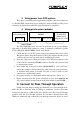
C. Dip Switch & Jumper Settings 1. On control board in display head Emulation mode (reach the switches from outside of back of the head) SW2 OFF ON SW1 OFF EPSON 2 X 20 NORITAKE 2 X 20 ON EPSON 4 X 26 IEE (CHINESE) 2 X 10 SW1 Push up to switch on SW2 RS232 protocol (Inside display head) Short JP1 19200, n, 8, 1 Open 9600, n, 8, 1 (default) 2.
1 –2 Short 2 –3 Short -Busy status of PD sent to host CTS, -Busy status of PD sent handshaking signal of pass through device JP2 to host as CTS and goes to host as DSR directly (default) DSR at the same time Note: There must be the pass through serial output device on the premounted pass through terminator connected to RS232 Out the 9 pin serial pass through port when JP2 is set to 2 –3 Short. Otherwise, the host computer may get a faulty condition in an attempt to write to this serial port. D.
V. MECHANICAL SPECIFICATIONS A. Mechanical Drawings 260.0 193.0 70.0 70.0 60.3 36.8 39.4 70.0 104.0 304.0 (Max. height) 200.0 200.0 104.0 Stroke (Lowest height) 41.0 41.0 41.0 220.0 110.0 B. Mechanical Function The pole of this customer display consists of 2 sections enabling adjustment on the height of the pole. The total height of this display is dependent on the pole adjustment, please refer to the drawings of last section The difference between maximal and minimal height is 104 mm.
VI. ELECTRICAL CHARACTERISTICS A. Power ON / OFF Sequence There are no deleterious effects associated with power ON and OFF of this display; however, rapid ON / OFF sequencing is not recommended. Neither data nor power connectors should be connected / disconnected while power is applied. B. Interface Signals All logic signals abide by the following convention: logic “1” is a “High”, logic “0” is a “Low”. C. Normal Operation Ratings Rated power dissipation: 3.75 W (max.) VII. OPTICAL CHARACTERISTICS A.
B. FUNDAMENTAL SPECIFICATION Number of display dot Effective display area Dot size LCD type Viewing angle Response time : : : : : : 160 x 32 179.15 (W) x 36.75 (H) mm 1.07 (W) x 1.10 (H) mm STN with backlight 80 degrees vertically, 60 degrees horizontally 250 ms (typical) VIII.