Aura Series (PP-7000II / PP-7000IIUSB) Thermal Printer Rev.: B1 IMPORTANT!!!! Please read carefully before using this printer Before opening the Top Hood, make sure there is no paper jam or cutter jam trouble. (Read page 3-4, 3-5 and Warranty Limit in the user’s Manual.
Federal Communications Commission Radio Frequency Interference Statement This equipment has been tested and found to comply with the limits for a Class A digital device, pursuant to Part 15 of the FCC Rules. These limits are designed to provide reasonable protection against harmful interference when the equipment is operated in a commercial environment.
Table Of Contents GETTING STARTED -- 1 -- 1 -- 1 -- 2 -- 3 -- 4 -- 5 -- 5 -- 6 QUICK START-UP . . . . . . . . . . . . . . . . . . . . . . . . 2 -- 1 -- 1 -- 1 -- 2 -- 2 -- 2 -- 2 -- 3 -- 7 -- 8 -- 8 -- 8 -- 9 -- 9 -- 10 -- 10 -- 11 -- 11 . . . . . . . . . . . . . . . . . . . . .1 CONGRATULATION . . . . . . . . . . . . . . . . . . . . . . 1 PRODUCT BRIEFING . . . . . . . . . . . . . . . . . . . . . 1 UNPACKING . . . . . . . . . . . . . . . . . . . . . . . . . . . . . 1 OPTIONS . . . . . . . . . . . . . .
GENERAL CLEANING . . . . . . . . . . . . . . . . . . . . 3 PRINT HEAD CLEANING . . . . . . . . . . . . . . . . . 3 TROUBLE SHOOTING . . . . . . . . . . . . . . . . . . . . 3 General problems . . . . . . . . . . . . . . . . . . . . . 3 Printing problems . . . . . . . . . . . . . . . . . . . . .3 Paper jam problems . . . . . . . . . . . . . . . . . . . 3 Auto cutter problems . . . . . . . . . . . . . . . . . . 3 Advanced analysis tool . . . . . . . . . . . . . . . . .
I. GETTING STARTED A. CONGRATULATION You have made a very wise decision by purchasing the easy loading; low noise; high resolution; light weight; high reliability thermal printer Aura (PP-7000II & PP-7000IIUSB) series of Posiflex products. This series of printers has been elegantly designed for a Point-Of-Sale, kitchen & kiosk application.
The Aura PP-7000II & PP-7000IIUSB supports a guillotine type auto cutter for paper partial cut and a manual cut mechanism. The Aura series also supports user’s company’s LOGO downloading for superior performance. It even supports some enhancement capability for reminder function to persons around. It can be used to drive a separately purchased kitchen bell for such reminder function in noisy environment.
Length of the interface cable depends on whether the order includes the power adaptor. When power adaptor is included, the interface cable is 6 ft long for stand alone application. When the power adaptor is not included in the order, the interface cable is a shorter one for integrated application in Posiflex POS system. g One of the power sources: a Power adaptor + power cord (depend on country type ordered).
E.
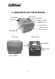
Rear View of PP-7000IIUSB Rear View of PP-7000II Frame Ground Parallel Connector USB Connector Frame Ground Serial Connector Peripheral Connector Power Connector F. INDICATORS • Power LED: green • Error LED: red • Paper Out LED: red G. OPERATING ENVIRONMENT • Place the printer on a sturdy, level surface. • Choose a place that is well ventilated and free of excessive dust, smoke or fume. • Do not put the printer under direct sunlight or near a heater.
• Since the paper roll is highly thermal sensitive, please keep them in a dark place that is 20º and 65% RH when not installed in the printer. • Use a grounded AC power outlet. • Use only the power cord and power adaptor furnished with the printer. • Do not use a power outlet of a circuit shared with any equipment that causes great electrical noise, such as motors. • Do not use a power outlet of a circuit shared with any equipment that uses a lot of power, such as a copier or a coffee maker.
• Use of volatile organic solvents such as alcohol, ester and ketone on thermal paper can cause discoloration. • Some adhesive tapes on thermal paper may cause discoloration or faded printing. • Use only products made from polyethylene, polypropylene or polyester for storage of thermal paper. If thermal paper touches anything includes phthalic acid ester plasticizer for a long time, the image formation ability may be reduced or the printed image may fade.
II. QUICK START-UP A. LOADING PAPER 1. Desk top application 1. Slide the hood lock toward the front of the printer to release the hood. 2. Raise the released hood wide open manually. 3. Drop the thermal paper roll inside the printer in the orientation as shown in the picture. 4. Close the hood back leaving the tail of the paper roll coming out of the opening between the hood and the top cover. Tear off excessive paper.
2. When to replace paper Whenever the printer gives paper out signal or a red line appears on the thermal paper, it is the proper timing for replacing the paper. Do not wait till the print engine is dragging the paper roll at the very end. Remove the leftover and replace a new paper roll as illustrated above to prevent excessive paper dust in the printer and consequently possibility for paper jam. B. CONNECTING CABLES PP-7000II PP-7000IIUSB 1.
please adjust in setup window the switch positions both 1, and 2 to ON leaving the rest unchanged as factory default setting. 3. USB connection The USB cable used to connect the USB interface printer PP-7000IIUSB to the USB port of a host has a type A USB connector at one end that is a more or less flat shape 4 pin connector and a type B USB connector at the other that is a more or less square shape connector.
Follow the wizard and browse to the folder that holds the driver and specify this location for the wizard. Keep on following the wizard and it will come to a “Finish”. The process in “Add/New Hardware Wizard” for Win98 is also very similar to what shown here for Win2000/XP. There are however some differences after this. For Win98 the left picture below will show up for a while and the USB serial converter driver will be installed automatically in the background.
Follow the wizard and browse to the folder that holds the driver and specify this location for the wizard again. The process for this stage USB serial port converter driver installation is quite similar to the last stage for the USB printer device driver.
port assignment setup will be required to use the USB printer as if a normal serial printer. The procedures described below may also be engaged any time whenever a re-assignment of the COM port number is required. Select “Start”, “Settings”, “System”, “Hardware”, “Device Manager” consecutively in the Windows screen and explode the item “Ports (COM & LPT)” to find the “Posiflex PP-7000IIUSB Thermal Printer” designated to a COM port number as in one of the pictures below.
the Posiflex USB interface thermal printer will operate the same way as if a RS232 serial printer connected on the COM port specified. Please note that it is allowed to apply more than one Posiflex USB printer in one setup because each Posiflex USB printer may carry different internal ID. The only point to watch is that you must assign each USB printer with a different virtual COM port number.
5. Power connection The power connector is a 3 pin jack between the peripheral connector and the parallel connector for PP-7000II and is at the rightmost for PP-7000IIUSB. Either a Posiflex supplied power adaptor or a printer power cable from a Posiflex POS system can be connected to this connector to supply power for this printer. During insertion of the power plug, be sure to hear the click to obtain a firm contact.
The header is printed in text mode and the rest part of this slip is printed in page mode. If FEED button is pressed at this moment, a font table will be printed in text mode again. To exit the test printing, please turn the printer off and on again. C. SPECIAL ADJUSTMENTS 1. Paper near end sensor The near end sensor for paper roll in the printer is now able to have the printer work with paper rolls of several bobbin sizes.
release the fixing screw to adjust the position of sensor head. The acceptable paper roll bobbin outer diameter is between 18 and 22mm. This adjustment allows sensor activation on paper roll overall diameter between 21 and 23.6 mm unless for too light bobbins. Remember, for smaller roll diameter, the sensor head should go higher. 2. Paper roll placement When the paper roll to put (back) in is Bobbin O.D. already nearly used up, the paper roll must be Bobbin I.D.
accessory of the printer. If the user uses narrower paper roll and requires more spacer plates, it can be purchased from Posiflex. 4. Paper cutting The paper advance after a protective cut is now set to 12 mm.
III. MAINTENANCE GUIDES A. MAINTENANCE GUIDE LINES • • • Always turn off and disconnect power before opening the cover. The areas around the print head and motor become very hot during and just after printing, do not touch them. When handling the interior of the thermal printer, please pay attention not to be hurt by any sharp edge of the metal parts. B. GENERAL CLEANING Please use soft hair brush or compressed air to clear away any dust or paper scraps accumulation inside the printer.
Before putting back the paper roll for printing, alcohol solvent must be dried completely. D. TROUBLE SHOOTING This section gives solutions to some printer problems you may have. 1. General Problems No LED lights up on control panel when switched on – Make sure that the power supply cables are correctly plugged into the printer, the power adaptor and to the power outlet. Make sure that power is supplied to the power outlet. If the outlet is controlled by a switch or timer, try use another outlet. 2.
If there is no paper jam and the print head is not overheated, turn off the printer and wait for half a minute then turn it back on. If the problem still remains, contact a qualified service person. Nothing can be printed with ERROR LED OFF – Try to run self test according to previous chapter to check if the printer itself works properly. If the self test passes, check the following: a. Check the connection of the interface cable at both the printer and computer ends.
3. Paper Jam Problems Paper is jammed inside the printer – Turn off the printer and open the print hood by releasing the hood lock. Remove the jammed paper and reinstall the paper roll. Close the hood properly and firmly. Then turn on the printer for operation. If the auto cutter is jammed, the print hood will be locked. Please first resolve the auto cutter problems per description in next item and then come back to deal with the paper jam. Never force open the print hood.
Lift transparent protective foil Open Cutter Cover when hood locked Turn the wheel downward till a hole in the plastic gear appears in this window 5. Advanced Analysis Tool This printer supports Hexadecimal Dump for experienced user to view exactly what data is received by the printer. This can be useful in finding software problems. To start the dump mode: Turn off printer; Open print hood; Hold down FEED button while turning printer on; Close the hood.
IV. SPECIFICATIONS A. PRINTER ITEM Printing method Effective printing width Thermal head configuration Printing speed Paper feed method Paper load method Auto-cutter capability Manual cutter Dot Pitch Input power type Input voltage Dimension (mm) Weight SPECIFICATION Thermal sensitive line dot method 64 mm 512 dots / line 180 mm /sec. Friction auto-feed Drop and use Partial cut (1 point at center left) Saw tooth blade 0.125 x 0.125 mm DC 24 V + / - 5 % 148 (W) x 199 (D) x 144 (H) 1.35 Kg net B.
C. POWER ADAPTOR ITEM INPUT VOLTAGE INPUT FREQUENCY INPUT CURRENT OUTPUT VOLTAGE OUTPUT POWER STATIC LOAD OUTPUT REGULATION MTBF EMI STANDARDS REQUIREMENT 100 V AC ~ 240 V AC 50 ~ 60 HZ 1.8 A MAX. @ 115 V AC + 24 V DC 60 W 0 A ~ 2.
V. TECHNICAL INFORMATION A. INTERFACES 1. Peripheral interface The connector for peripheral control is a 6P6C RJ11 jack with the following pin assignment. The best recommended cash drawers to this connector are Posiflex CR3100, CR3200, CR4000 and CR4100. Using the cable 20863018001 (CCBLA-180-1) delivered with the cash drawer, the Aura series can control one dedicated cash drawer. However, by using an optional split cable 20867023800 (CCBLA-238), Aura series controls two cash drawers through this connector.
B. SETUP WINDOW On bottom cover of the Aura series thermal printer, there is screwed a metal plate for setup window. In this window, there is a 8 position DIP switch for printer setup. Please use proper tool to change the switch setting when necessary. The switch position counting starts from the nearest edge of printer. The ON direction points to the connector area of the printer. The OFF direction points to the power switch. The functions of each position may evolve with the revisions of the firmware.
Switch position 4 defines the handshaking method in serial interface. When it is set to ON, the printer transmits an “XOFF” for busy and sends an “XON” for not busy. When it is set to OFF, the printer signifies the busy status over hardware signals that can be detected by the host as “DSR” or “CTS”. When parallel interface is used, both switch positions 3 and 4 should be set to OFF. For switch position 5, if the switch is set to ON, the busy signal is sent to host only when input buffer is full.
Switch Position 1 2 3 4 5 6 7 8 Serial interface w/ OFF OFF OFF OFF OFF OFF OFF OFF auto cutter Parallel interface w/ ON ON OFF OFF OFF OFF OFF OFF auto cutter C. INTERNAL SWITCH There is an extra internal 4 position DIP switch in PP7000II for more technical settings. To access these setup, please first turn off the printer power and disconnect every cable from the printer. Remove 4 screws from bottom of printer and remove the plastic bottom cover with the power switch pressed.
D. SOFTWARE COMMANDS The Aura thermal printer supports all commands applicable to Epson printer TM-T88II. The only difference is the smoothening command in enlarged text fonts. Please visit our web site http://www.posiflex.com or http://www.posiflex.com.tw for detail description of the supported commands if required. 1. Paper out alarm When Paper End signal is detected, the printer keeps on intensive beeping and stops receiving data till the signal is neutralized.
This command defines length of beep as m seconds when beep command is received. When m = 0, default applies. ESC ‘p’ m n1 n2: Kitchen bell drive command (m = ‘0’, 0 ≦ n1 ≦ n2 ≦ 255) Hexadecimal codes are: 1B 70 m n1 n2 This command can be used to drive a kitchen bell purchased from Posiflex when this printer is used as a kitchen printer and the environment could be so noisy that the beeper for reminding the kitchen staff of the printing can be not loud enough.
E. CHARACTER CODE PAGES Aura PP-7000II & PP-7000IIUSB series support all code pages and international character sets applicable to Epson printer TM-T88.
If any undefined code (<00> to <1F>) or an undefined , , or command sequence beyond these tables is received, the code or the sequence of codes will be discarded. (However, when image print data, character registration data, or command parameters are received, they are handled as ordinary data.) The user may visit our web at http://www.posiflex.com.tw or http://www.posiflex.com for a view of the fonts in the code pages and character sets.