
Printer User Manual


Part 2
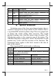
PIN #
Definition
Description
1 FG Frame ground
2 CRB
Drawer kick for cash drawer controlled by
software command Esc p 0 n1 n2
3 SENSE Input peripheral status
4 VCC + 24 V DC supply
5 CRA
Drawer kick for cash drawer controlled by
software command Esc p 1 n1 n2
6 SG Signal ground
B. SETUP WINDOW
On bottom cover of the Aura series thermal printer, there is
screwed a metal plate for setup window. In this window, there is
a 8 position DIP switch for printer setup. Please use proper tool
to change the switch setting when necessary. The switch
position counting starts from the nearest edge of printer. The
ON direction points to the connector area of the printer. The
OFF direction points to the power switch. The functions of each
position may evolve with the revisions of the firmware. The
information below applies to the latest version to the date of
print of this manual.
This 8 position DIP switch works as following:
Switch
position
ON OFF
1
2
RS232 baud rate definition or Parallel interface definition
(ref. separate table below)
3 Even parity None parity
4 XON handshaking Hardware handshaking
5 Busy on “buffer full” Busy on “off line”
6 Immediate cut Protective cut
7 CR code effective CR code ineffective
8 Factory internal setting Application standard mode