TM PST KB136 SERIES QWERTY KEYBOARD
TM
TM TABLE OF CONTENTS OVERVIEW . . . . . . . . . . . . . . . . . . . . . . . . . . . . . . . . . . . . . . . . . . . . . . . 1 - 1 SCOPE . . . . . . . . . . . . . . . . . . . . . . . . . . . . . . . . . . . . . . . . . . . . . . 1 - 1 FEATURES . . . . . . . . . . . . . . . . . . . . . . . . . . . . . . . . . . . . . . . . . . . 1 - 1 MODEL NUMBERS . . . . . . . . . . . . . . . . . . . . . . . . . . . . . . . . . . . . 1 - 2 ACCESSORIES . . . . . . . . . . . . . . . . . . . . . . . . . . . . . . . . . . . .
TM COMMAND LISTING IN VIEW MODE . . . . . . . . . . . . . . 4 - 6 COMMAND LISTING IN ASCII-CODE EDITING MODE . . . . . . ................................................ 4 - 7 COMMAND LISTING IN SCAN CODE EDITING MODE . . . . . . ................................................ 4 - 8 ANSWER BACK CODE . . . . . . . . . . . . . . . . . . . . . . . . . . 4 - 9 HARDWARE LIMITATION . . . . . . . . . . . . . . . . . . . . . . . . 4 - 9 SHORTCUT UTILITY (RWM.EXE) . . . . . . . . . . . . . . . . . . . . . . .
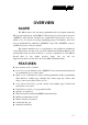
TM OVERVIEW SCOPE The KB136 unit is the optional programmable keyboard segment within the PST systems replacing the original KB112. This keyboard provides in the lower part a “QWERTY” keyboard that resembles the standard PC keyboard and at the top a matrix of 3 by 17 locations for freely programming purpose. Nevertheless, there are 2 more programmable keys within the “QWERTY” region. The “QWERTY” region is available for layout of various countries.
TM MODEL NUMBERS MODEL NUMBER COUNTRY / LANGUAGE PSTKBQRTY-FR French PSTKBQRTY-GR Germany PSTKBQRTY-IT Italy PSTKBQRTY-NL Netherlands PSTKBQRTY-PO Portugal PSTKBQRTY-SP Spain PSTKBQRTY-SV Sweden / Finland PSTKBQRTY-UK United Kingdom PSTKBQRTY-US United States ACCESSORIES When the KB136 QWERTY keyboard is supplied with a PST system, the original 112 key programmable keyboard is replaced by the KB136 QWERTY keyboard.
STANDARD LAYOUTS l l l l l l l l l FRANCE GERMANY ITALY NETHERLANDS PORTUGAL SPAIN SWEDEN/FINLAND UNITED KINGDOM UNITED STATES TM 2-1
TM 2-2 FRANCE ² 1 2 3 & é " A Z 4 # ' E 5 { ( R 6 [ T 7 8 ` _ ¦ è Y U 9 \ ç I 0 ° à @ ) O + ] = P W ñ Ctrl S ÿ D X Alt F C G V H B J N K ? , L £ . ; M / : Alt Gr 9 4 5 6 2 3 00 .
GERMANY ° ! " § $ % & / ( ) = ? ` 1 2 ² 3 ³ 4 5 6 7 { 8 [ 9 ] 0 } β \ ´ Q W E R T Z U I O P U @ ò A Y ñ Strg S ÿ D X F C G V H B J N K M L O ; : _ µ , .
TM 2-4 ITALY ¦ ! " £ $ % & / ( ) = ? \ 1 2 3 4 5 6 7 8 9 0 ' Q W E R T Y U I O P 7 ì Z ñ Ctrl S ÿ D X Alt F C G V H B J N K M L ° § ò @ à # ù : _ , . - Alt Gr ÿ 4 5 6 1 2 3 ] Invio ç ; 9 Pag * [ + é è A 8 Fine ñ Ctrl 0 Ins Pag 00 .
NETHERLANDS § ! " # @ ¬ 1 ¹ 2 ² 3 Q W $ _ ( ) ' ? ³ 4 ¼ 5 ½ 6 ¾ 7 £ 8 { 9 } 0 / E % R & T Y U I O 7 \ P A D Z X F « ÿ C » G V ¢ H J K L B N M PgUp 4 5 6 2 3 ± ` 1 + ´ End ; : = [ µ , .
TM 2-6 PORTUGAL ¦ ! " # $ % & / ( ) = ? » 7 \ 1 2 @ 3 £ 4 § 5 6 7 { 8 [ 9 ] 0 } ' « Home Q Caps Lock A ÿ E S Z ñ Ctrl W D X Alt R T F C Y G V U H B I J N O K M P L Ç ; : _ , . - Alt Gr ÿ * ` + ´ 8 9 PgUp 4 5 6 ª 1 2 3 º End ñ Ctrl 0 Ins PgDn 00 .
SPAIN ª " · $ % & / ( ) = ? ¿ 7 ¦ 2 @ 3 # 4 5 6 ¬ 7 8 9 0 ' ¡ Inicio ! º \ 1 Q W E R T Y U I O * [ + P ` A Bloq Mayús ÿ D F G H J K L Ñ X C V B N M ; : _ , . - Alt Gr Alt ÿ { 9 Re Pág 4 5 6 1 2 3 ] Ç ´ Z ñ Ctrl S 8 } Fin ñ 0 Ins Av Pág 00 .
TM 2-8 SWEDEN/FINLAND ½ ! " § 1 2 @ 3 Q Caps Lock W A ÿ £ 4 E S Z ñ Ctrl # R D X Alt $ % & / ( ) = ? ` 5 6 7 { 8 [ 9 ] 0 } + \ ´ T F C Y G V U H B I J N O K M O A ; : _ , .
UNITED KINGDOM ¬ ! " £ $ % ` 1 2 3 4 5 Q Caps Lock A E S Z ñ Ctrl W R D X T F C 6 Y G V & * ( ) _ + 7 7 8 9 0 - = Home U H B I J N O K L } [ ] @ ; ' . Alt Gr Alt { : M , ÿ P ÿ # ? ¦ / \ 8 PgUp 4 5 6 1 2 3 End ñ 9 0 Ins PgDn 00 .
TM 2 - 10 UNITED STATES ` Tab ! @ # $ % 1 2 3 4 5 Q Caps Lock A E S Z ñ Shift Ctrl W R D X T F C 6 Y G V & * ( ) _ + 7 7 8 9 0 - = Home U H B I J N O K L Alt { } ¦ [ ] \ : " ; ' M Enter ? , ÿ P . Alt ñShift / ÿ Ctrl 8 9 PgUp 4 5 6 1 2 3 End 0 Ins PgDn 00 .
TM INSTALLATION HARDWARE INSTALLATION To install KB136 into a PST system originally equipped with KB112, the user should disassemble the KB112 from the PST system according to the instructions given in the Technical Manual of respective PST system. After this disassembly, there are three cables coming from the inside of the PST system, namely, a 2 pin cable for the standby LED, a 4 pin cable for KB signal and a DIN 5 pin cable for the external KB connector.
TM UTILITY INSTALLATION There are in total three methods to program the programmable keys in KB136 QWERTY keyboard: “RWM.EXE” the straightforward direct read/write programming utility; “KBM.EXE” the normal programming utility and the “Hot Key Programming” most suitable to modify the key contents of one or two keys. Installation procedures are required for utilities “KBM.EXE” and “RWM.EXE”. In the utility diskette, there is a file named “INSTALL.
TM PROGRAMMING HOT KEY PROGRAMMING The KB136 programmable keyboard supports the “hot key programming” method which is most useful in instant modification of a few keys in a preprogrammed keyboard without entering the more sophisticated programming utility. Of course, the user may also use this feature to program through out all 51 keys (3 rows, 17 columns) by 5 pages (LP and L1 to L4) at will.
TM key while pressing the “PRT SC” (“Print Screen”) key on the PC or PS-2 keyboard. And by doing so, the KB136 will give 2 beeps to notify that it is ready to receive the identification of which key to be programmed. Right after the “hot key” is released, the user shall press the key to be programmed on the programmable keyboard once to identify which key to be programmed.
TM EXIT “HOT MODE KEY PROGRAMMING” After the intended content of the key is completely entered, the user shall press the “hot key” again to notify the end of “hot key programming”. The programmable keyboard will give one beep to signify the normal exit of the “hot key programming” mode.
TM PROGRAMMING UTILITY (KBM.EXE) GENERAL Using the “KBM” utility for KB136 is quite similar to the way to use the “KBM” utility for KB112 though they may be of different versions and should be used distinctively. However, the screen display for KB136 is different from that for KB112 as the physical layout is different. Therefore, the screen display is explained as the following, whilst the user may refer to the relevant Technical Manual of PST systems or the web site for the rest.
TM Posiflex Programmable Keyboard Utility vx.xx.
TM COMMAND LISTING IN VIEW MODE ESC – quit the keyboard programming program F1 – get help on command list F3 – enter the configuration screen F5 – enter ASCII-code editing mode F8 – enter scan-code editing mode F10 – quit the keyboard programming program Ins – toggle insert/overwrite status for editing (default = insert) Del – delete the content of the key where cursor stays Home – go to column A of same page same row End – go to column I of same page same row PgUp – go to one page less in cyclic manner Pg
TM Alt-W – write key definitions to the programmable keyboard Alt-X – quit the keyboard programming program any other key stoke – will be taken as an input in ASCII-code editing mode, and will give no influence if the current key was last edited in scancode editing mode COMMAND LISTING EDITING MODE IN ASCII-CODE ESC – enter view mode F1 – get help on command list of ASCII- code editing mode F5 – enter view mode F8 – enter view mode F10 – enter view mode BkSp – delete the character to the left of cursor
TM any other key stoke – will be taken as an input in ASCII-code editing mode. COMMAND LISTING IN SCAN CODE EDITING MODE ESC – leading code to enter scan code of any key after it into key-content, except “ESC” + “F” for utility version since 2.15.xx ESC-F – leading code of arbitrary release code for utility version since 2.15.xx. usually used to release “CTL”, “ALT” or “SHF”.
TM any other displayable key stoke – will be taken as an input in scan-code format. any other non-displayable key stroke – will have no influence ANSWER BACK CODE Programming the answer back codes of the 6 position electronic key-lock is also very easy as they are included in the keyboard programming with the locations coded as “KLP”, “KL0”, “KL1”, “KL2”, “KL3” and “KL4” in the key-layout map of page L1.
TM SHORTCUT UTILITY (RWM.EXE) The feature of this RWM.EXE is designed mainly for the off-line programming purpose and is very useful in quick reproduction of the preprogrammed contents of the programmable keyboard. In such application, the user should have either the preprogrammed keyboard or the preprogrammed file with “.tpl” extension name which is the result of the keyboard programming. The user may use RWM.EXE to directly transfer the programmed result of the programmable keyboard to a “.
TM DETAILS IN PROGRAMMING Please refer to our web site for every detail in programming this KB136. The following simplified guide severs as a concise tool for instant application.
TM 5-2
TM APPLICATION KEYBOARD CONSTRUCTION This keyboard is constructed of three parts on the top surface (ref. Fig. 6-1). A 6 position turning key switch area is at the upper right corner, a 17 x 8 matrix push key switch structure occupies most of the top surface and a up-down slot near the left edge is designed for the Magnetic Stripe Reader options. Push key switch matrix structure 6 position key switch area MSR slot Fig.
TM L2 L1 L3 L2 L4 LP Stand-By L1 L3 L4 LP POWER Stand-By POWER Caps Lock Num.Lock Caps Lock Fig. 6 – 2 Layout in 6 position key switch area The top left LED is for stand-by indication, the top right LED is the power-on indicator and the bottom right LED is the Cap-Lock indicator for the “QWERTY” keyboard. For the KB136 manufactured after year 1999, another LED at the bottom left is added to indicate Num-Lock status of the numerical keypad as shown in the right in Fig. 6-2.
TM PUSH KEY SWITCH MATRIX The major part on the keyboard surface is constructed in a 17 x 8 matrix providing a possibility of maximum 136 key positions available. This is why this keyboard is named as KB136. However, as indicated before, while the upper 17 x 3 matrix remains in matrix and page dependent, the lower part is organized in “QWERTY” format.
TM Fig. 6 – 3a Fig.
TM Fig. 6 – 3c It is very important to correctly orientate the key tops before they are inserted into the keyboard frame. Failure to do this could result in permanent damage. Looking into the guide hole on the keyboard frame, there is a tab inside the bottom side wall (ref. Fig. 6-4). Examining the bottom square stem of a single key top, there is a springy latching tab on one side (ref. Fig. 6-5a).
TM Key top Double key top Latching tab Latching tab Latching tab Fig. 6 – 5a Fig. 6 – 5b When any key top is to be inserted onto the keyboard frame, the tab on the inside wall of the key top guide hole must mate a corresponding springy latching tab as illustrated above. In this way, the matching stem of a double key must be either at the bottom when the double key is “vertically” aligned or at the right of the key coverage area when the double key is “horizontally” aligned.
TM PRELOADED PATTERN This keyboard is preloaded with some data in the “LP” page of the programmable area as indicated below to help the user’s application at the moment he/she receives this programmable keyboard. Insert Home PgUp Esc F1 F2 F3 F4 F5 F6 F7 F8 Delete End PgDn F9 F11 F10 F12 Print Scroll Pause Num Lock Screen Lock ~ ` Tab ! 1 | @ 2 Q W $ 4 E % 5 R ^ 6 T * 8 & 7 Y U ( 9 I ) 0 O _ P A S Z ñ Shift ÿ D X Alt F C G V H B J N K M : ; L < , > .
TM 6-8
TM HARDWARE DETAILS PCB LAYOUT CONNECTORS Position Connector Type Function JP1 DIP 5 pin jack External KB connector JP3 8 x 1 header 6 position key lock JP5 4 pin header 90° Internal KB JP6 11 pin lock connector Narrow tongue of membrane JP12 (7 x 1 header) Reserved alternative external KB connector JP13 (Mini DIN 6 pin jack) Reserved alternative external KB connector JP15 16 pin lock connector Wide tongue of membrane JP20 2 pin header Cap Lock LED JP21 2 pin header (Num Lock
TM JUMPER SETTING POSITION FUNCTION JUMPER SHORT JUMPER OPEN J10 JIS II/ISO JIS II MSR ISO MSR J13 ALT + NUM OFF ON J14 TRACK 1 ON OFF J15 TRACK 3 ON OFF J16 TRACK 2 ON OFF J17 Leading & ending sentinel OFF ON JP183 STATUS JP184 STATUS FUNCTION 1-2, 3-4, 5-6, 7-8 short All open MSR enabled All open 1-2, 3-4 short MSR disabled 7-2
TM PART NUMBERS Part Number Description PSTKB136 Stroke type keyboard w/o MSR PSTKB136MR2 Stroke type keyboard with 2 track MSR PSTKB136MR3 Stroke type keyboard with 3 track MSR PSTKB136MRJS2 Stroke type keyboard with JIS II MSR PSTKB136CPUMR Keyboard controller CMSRCATRIGE-2 MSR module 2 tracks CMSRCATRIGE-3 MSR module 3 tracks CMSRCATRIGE-4A MSR module JIS II PSTKBELCK6PASY 6 position key lock with wafer assembly PSTKB112EKEY 4 key set for 6 position key lock PSTKBMECHKEY Keyboard
TM 8-2