
Computer Keyboard User Manual


3 - 1
TM
INSTALLATION
HARDWARE INSTALLATION
To install KB136 into a PST system originally equipped with KB112, the user
should disassemble the KB112 from the PST system according to the instructions
given in the Technical Manual of respective PST system. After this disassembly, there
are three cables coming from the inside of the PST system, namely, a 2 pin cable for
the standby LED, a 4 pin cable for KB signal and a DIN 5 pin cable for the external
KB connector.
The user shall connect these three cables to the proper connectors in the
KB136 assembly as shown in the example below. Unlock the mechanical lock, place
the programmable keyboard down and back to the position, lock the mechanical lock
and screw on the 2 bottom screws as in reverse order of the disassembly of the
keyboard unit. The KB136 is then well installed.
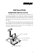
Fig. 3 – 1 Cable connection
Cable for standby LED
4 pin cable for KB signal
External KB cable