PFC-7500 Series Installation Manual Fire Alarm Communicator (All specifications subject to revision.) 5757 Phantom Dr. Ste 125 • P.O. Box 42037 • St. Louis, MO 63042 (866) 240-1870 • (314) 595-6900 • FAX (800) 768-8377 www.pottersignal.
MODEL PFC-7500/PFC-7501 COMMAND PROCESSOR INSTALLATION GUIDE FCC NOTICE This equipment generates and uses radio frequency energy and, if not installed and used properly in strict accordance with the manufacturer’s instructions, may cause interference with radio and television reception.
Table of Contents Panel Specifications 1.1 1.2 1.3 1.4 1.5 1.6 1.7 Power Supply........................................................................................... 1 Communication........................................................................................ 1 Panel Zones.............................................................................................. 1 Remote Annunciators (Alphanumeric or LED Keypads)........................ 1 Auxiliary Outputs.................................
Form C Relay Outputs 12.1 Description............................................................................................. 12 Annunciator Outputs 13.1 13.2 Description............................................................................................. 12 Harness Wiring....................................................................................... 12 Telephone RJ Connector 14.1 14.2 14.3 Description.................................................................................
Panel Specifications 1.1 Power Supply Primary Power Input: 16.5 VAC 40 VA (Model WLT wire-in) or 12/24 VDC from Fire Alarm Control Panel (FACP) Standby Battery: One or two 12 VDC batteries Auxiliary Output: 500mA at 12 VDC Bell Output: .6 Amps at 12 VDC (PFC-7501 only) Smoke Detector Output: 100mA at 12 VDC (PFC-7501 only) All circuits inherent power limited except the red battery wire. * For Commercial Fire installations, see the Compliance Instructions section. 1.
Introduction 2.1 Description 2.2 Zone Expansion The Potter PFC-7500 Series Commercial Fire Panels are powerful 12 VDC fire alarm communicators with battery backup that can also be powered from the 12 or 24 VDC auxiliary output of a Fire Alarm Control Panel (FACP). Each panel provides one Class A (Style D) fire zone and four Class B (Style A) powered fire zones with reset capability for 2-wire smoke detectors, relays, or other latching devices.
System Components 3.1 Description 3.2 PFC-7501 Wiring Diagram A basic PFC-7500 Series system is made up of the alarm panel with built-in communicator, an enclosure, a 16.5 VAC wire-in transformer, and a 12 VDC 7.0 Ah battery. You can add up to two alphanumeric keypads and one or more LED keypads to the panel and also connect control and annunciating devices to the panel Form C and annunciator outputs. Refer to the Power Requirements section in this guide when calculating power requirements.
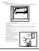
PFC-7500 Wiring Diagram The PFC-7500 system below shows some of the accessory devices for use in various applications. USE MARKING Commercial Protected Premises Control Unit J5 J4 Silence/Reset Header S S Telephone Connections POWER LIMITED All circuits on the Model PFC-7500 comply with the requirements for inherent power limitation and are Class 2 except the red battery wire.
Installation 4.1 Mounting the Enclosure Mount the metal enclosure for the PFC-7500 Series panels in a secure, dry place to protect the panels from damage due to tampering or the elements. It is not necessary to remove the PFC-7500 or PFC-7501 PCB when installing the enclosure. 3/4" x 1/2" Knockout Two 1 3/4" Wire Openings 3/4" x 1/2" Knockouts Transformer Knockout Extra Deep 3 3/4" Cabinet Figure 3: Mounting the Enclosure 4.
4.3 Mounting Keypads Potter keypads have removable covers that allow you to easily mount the base to a wall or other flat surface. After installing the keypad mounting anchors and bringing the keypad wiring from the panel through the wall, mount the base and connect the keypad wire harness leads to the keypad wiring. Next, attach the keypad wire harness connector to the pin connector on the keypad circuit board and install the cover.
Primary Power Supply 5.1 Installing the Transformer The transformer requires an unswitched 120 VAC 60 Hz electrical outlet with at least 350mA of available current. Never share the transformer output with any other equipment. The 120 VAC circuit is not power limited. To mount the Model WLT Transformer to a single-gang box adjacent to the PFC-7500 Series enclosure, follow the steps below. Refer to Figure 6 as needed. 1. Remove the lower knockout from the PFC-7500 Series enclosure. 2.
Secondary Power Supply 6.1 Battery Terminals 3 and 4 Connect the black battery lead to terminal 4 on the panel and then to the negative terminal of the battery. The negative terminal connects to the enclosure ground internally through the PFC-7500 Series panel circuit board. Connect the red battery lead to terminal 3 on the panel and then to the positive terminal of the battery. Observe polarity when connecting the battery. The PFC-7500 Series panels are capable of recharging two 7.7 Ah batteries (15.
6.6 PFC-7500 Series Power Requirements 6.7 PFC-7500 Series Standby Battery Calculations During AC power failure, the PFC-7500 Series panels, and all auxiliary devices connected to the panels, draw their power from the battery. All devices must be taken into consideration when calculating the battery standby capacity. Below is a list of the power requirements of the PFC-7500 Series panels.
Bell Output 7.1 Terminal 5 (PFC-7501 Only) Terminal 5 supplies 12 VDC Bell Output to power alarm bells or horns. The output is rated for a maximum of 1.5 Amps. This output can be steady or temporal depending upon the Bell Action specified in Output Options programming. Terminal 10 is the ground reference for terminal 5. See the Notification Appliance section for a list of approved notification appliances and the Wiring Diagrams for connections 4-Wire Smoke Detector Power 8.
Class B (Style A) Fire Zones 11.1 Description Terminals 15 to 22 are the Class B (Style A) fire zones on the PFC-7500 Series panels. These zones are suitable for connecting powered or non-powered fire devices. For programming purposes, these zones are designated 2 to 5. The maximum line impedance is 100 Ohms. The zone configurations on terminals 15 to 22 are described below: Terminal 15 17 19 21 11.
Form C Relay Outputs 12.1 Description The PFC-7500 Series panels can provide two programmable auxiliary Form C (SPDT) relays when equipped with plugin relays in sockets OUTPUT 1 and OUTPUT 2. Each relay is rated for 1 Amp at 30 VDC (allows .35 power factor). Each output provides one Common, one Normally Open, and one Normally Closed terminal. Field wiring for the Form C relays connects to the 6-position terminal strip on the lower right corner of the PFC-7500 Series boards.
14.3 Notification Registered terminal equipment must not be repaired by the user. In case of trouble, the device must be immediately unplugged from the telephone jack. The factory warranty provides for repairs. Registered terminal equipment may not be used on party lines or in connection with coin telephones. Notification must be given to the telephone company of: a. The particular line(s) the service is connected to b. The FCC registration number c. The ringer equivalence d.
Listed Compliance Specifications 18.1 Introduction 18.2 NFPA For applications that must conform to a local authorities installation standard or a National Recognized Testing Laboratory certificated system, please see the following sections. This equipment should be installed in accordance with the National Fire Alarm Code, ANSI/NFPA 72, (National Fire Protection Association, Batterymarch Park, Quincy, MA 02269).
20.5 Remote Station Protective Signaling Systems 20.6 Remote Annunciators 60 hours of standby battery must be provided. Up to two 12 VDC, 7.0 Ah batteries may be used. See standby battery calculations. The PFC-7500 may be used to provide two reversing polarity telephone connections instead of dual phone lines. See the PFC-7500 Installation Instruction sheet for wiring details. At least one Model RA-7630 or RA-7692 Remote Annunciator must be used on the system.
Wiring Diagrams 22.1 SNM with NAC Extender To panel zone To panel alarm output To panel terminal 7 To panel zone To panel terminal 10 Normal/Silence Switch Potter Model SNM 45mA @ 12 VDC The SNM Notification Appliance Circuit Module in alarm draws up to 31mA through its Terminal 3 Alarm Input and 45mA from its Terminal 1 Aux Power Input.
22.
.3 SNM Class B Style W using Multiple Notification Appliances TAM Module MAIN BACKUP SILENCE/RESET PUSH FOR ONE SECOND J13 S ilence/Reset Header Telephone Connections Panel Reset S ilence/Reset B utton J10 Trouble Annunciator Header PFC-7500 SeriesCommercial Fire Command Processor Panel AC B+ B- BELL SM K RED YEL GRN BLK Z1A + Z1A- Z1B + Z1B- Z2+ Z2 - Z3+ Z3 - Z4+ Z4 - Z5+ Z5 - OUTPUT 2 AC OUTPUT 1 r J14 Bell Monitor J11 1 2 3 4 5 6 7 8 9 10 11 12 13 14 15 16 1
22.
22.
22.
PFC-7500 Connection to FACP MAIN BACKUP Silence/Reset Header Telephone Connections Panel Reset Silence/Reset Button J14 Bell Monitor J10 Trouble Annunciator Header PFC-7500 Commercial Fire Panel AC AC +B 1 2 3 Relay Sockets for Optional Form C Outputs on J11 -B BELL SMK RED YEL GRN BLK Z1A+ Z1A- Z1B+ Z1B- Z2+ Z2- Z3+ Z3- Z4+ Z4- Z5+ Z54 5 6 7 8 9 10 11 S 12 13 14 S S 15 16 17 18 19 20 21 S W 120 VAC 60Hz 350mA W Zone 1 DC Mode Wiring When the PFC-7500 is used in the DC
PFC-7500/7501 PROGRAMMING SHEET Name __________________________________ Account Number__________________________Date _______________ Address ________________________________ City ________________ State _______________Zip ________________ COMMUNICATION Communication Type 2nd Phone Line Account Number DTMF Receiver 1 Alarm Supv/Trouble Test Report Backup NONE DD 4-2 CID NO YES _ _ _ _ _ (DD range = 1 to 65535) (4-2 or CID range = 1 to 9999) NO YES NO NO NO NO YES YES YES YES REMOTE OPTIONS Remote Key Manuf