IMPORTANT MANUAL Do Not Throw Away OPERATOR'S MANUAL WARNING: MODEL: Read this Manual and follow all Warnings and Safety Instructions, Failure to do so can result in serious injury. DB27H48YT LAWN TRACTOR ALWAYS WEAR EYE PROTECTION DURING OPERATION Visit our website: www.poulan-pro.
SAFETY RULES Practices for Ride-On Safe Operation IMPORTANT: THIS CUTTING MACHINE IS CAPABLE OF AMPUTATING HANDS Mowers AND FEET AND THROWING OBJECTS FAILURE TO OBSERVETHE FOLLOWINGSAFETY INSTRUCTIONSCOULD RESULTIN SERIOUS INJURYOR DEATH • WARNING: In order to prevent accidental starting when setting up, transporting, adjusting or making repairs, always disconnect spark plug wire and place wire where it cannot contact spark plug.
SAFETY RULES Practices for Ride-On Safe Operation III. CHILDREN Tragic accidents can occur if the operator is not alert to the presence of children. Children are often attracted to the machine and the mowing activity. Never assume that children will remain where you last saw them, • Keep children out of the mowing area and in the watchful care of a responsible adult other than the operator. • Be alert and turn machine off if a child enters the area.
PRODUCT SPECIFICATIONS CONGRATULATIONS on your purchase of a new tractor. It has been designed, engineered and manufactured to give you the best possible dependability and performance. Gasoline Capacity and Type: 4.0 Gallons Unleaded Regular Oil Type (API-SG-SL): SAE 30 (above 32°F) SAE 5W-30 (below 32°F) Oil Capacity: W/Filter: 4.0 Pints W/O Filter: 3.75 Pints Spark (Gap: Champion Plug: .040") Ground Speed (MPFI): QC12YC Forward: Reverse: 5.5 2.
UNASSEMBLED PARTS Steering Wheel Seat Steering Wheel Adapter Steering Wheel Insert (1) Washer @ 17/32 x 1-3/16 x 12 Gauge (1) Large Flat Washer (1) Knob Steering Sleeve I_ Gauge Wheels f 0 @ 0 0 o (4) Adjusting Bar (4) Washers 3/8 x 3/4 x 14 Ga.
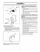
ASSEMBLY Your new tractor has been assembled at the factory with exception of those parts left unassembled for shipping purposes, To ensure safe and proper operation of your tractor all parts and hardware you assemble must be tightened securely, Use the correct tools as necessary to insure proper tightness.
ASSEMBLY SEAT SHOULDER BOLT TO ROLL TRACTOR OFF SKID (See Operation section for location and function of controls) • • SEAT PAN • • Press lift lever plunger and raise attachment lift lever to its highest position, Release parking brake by depressing clutch/brake pedal.
ASSEMBLY TO ATTACH NOSE ROLLER • (See Fig. 4) INSTALL MOWER AND DRIVE BELT (See Figs. 6 and 7) Assemble brackets "A" and "B" to the inside of mower mounting brackets as shown. Tighten securely. Be sure tractor is on level surface and mower suspension arms are raised with attachment lift control. Engage parking brake. • Cut and remove ties securing anti-sway bar and belts. Swing anti-sway bar to left side of mower deck. • Slide mower under tractor with deflector shield to right side of tractor.
ASSEMBLY LOCK BRACKET ELECTRIC CLUTCH PULLEY BELT TENSION ROD (DISENGAGED POSITION) CHASSIS BRACKET FRONT MOWER BRACKET . _.; _ FRONT SUSPENSION BRACKETS DOUBLE LOOP I RETAINER SPRING GAUGE WHEEL FLANGED PIN FRONT PLATE ASSEMBLY SINGLE LOOP RETAINER SPRINGS DOUBLE LOOP RETAINER SPRING ANTI-SWAY BAR USE PLIERS FOR RETAINER SPRINGS DEFLECTOR SHIELD SUSPENSION ARMS DOUBLELOOP RETAINER SPRING(OUTWARD POINTING DECK PINS) LOOP UP FIG.
OPERATION These symbols may appear on your tractor or in literature supplied with the product, Learn and understand their meaning, REVERSE NEUTRAL H L HIGH LOW IXI FAST CHOKE SLOW IGNITION SWITCH ENGINE OFF REVERSE OPERATION ENGINE ON ENGINE START PARKING BRAKE PARKING BRAKE LOCKED PARKING BRAKE UNLOCKED SYSTEM(ROS) oi t OVER TEMP LIGHT FUEL OIL PRESSURE BATTERY REVERSE ATTACHMENT CLUTCH DISENGAGED ATTACHMENT CLUTCH ENGAGED LIGHTS ON FREE WHEEL Models only) & Failure MOWER HEIG
OPERATION KNOW YOUR TRACTOR READ THIS OWNER'S MANUAL AND SAFETY RULES BEFORE OPERATING YOUR TRACTOR Compare the illustrations with your tractor to familiarize yourself with the locations of various controls and adjustments, Save this manual for future reference, IGNITION HOURMETER POSITION AMMETER CHOKECONTROL ATTACHMENT ,CLUTCH SWITCH THROTTLE CONTROL PLUNGER ATTACHMENT LIFT LEVER CLUTCH/BRAKE PEDAL KNOB LIGHT SWITCH BRAKE FREE WHEEL CONTROL CONTROL LEVER 2854 FIG.
OPERATION The operation of any tractor can result in foreign objects thrown into the eyes, which can result in severe eye damage. Always wear safety glasses or eye shields while operating your tractor or performing any adjustments or repairs. We recommend a wide vision safety mask over spectacles or standard safety glasses. HOW TO USE YOUR TO SET PARKING TRACTOR IMPORTANT: LEAVING THE IGNITION SWITCH IN ANY POSITION OTHER THAN "STOP" WILL CAUSE THE BATTERY TO BE DISCHARGED, (DEAD). BRAKE (See Fig.
OPERATION TO ADJUST GAUGE WHEELS (See Fig.
OPERATION Remove oil fill cap/dipstick and wipe clean, reinsert the dipstick and screw cap tight, wait for a few seconds, remove and read oil level, If necessary, add oil until "FULl" mark on dipstick is reached. Do not overfill, For cold weather operation you should change oil for easier starting (See "OIL VISCOSITY CHART" in the Maintenance section of this manual).
OPERATION WARM WEATHER STARTING (50° F and above) • When engine starts, slowly push choke control in until the engine begins to run smoothly. If the engine starts to run roughly, pull the choke control out slightly for a few seconds and then continue to push the control in slowly. • The attachments and ground drive can now be used.
MAINTENANCE AS YOU COMPLETE R EGU LARSE RVlCE Check Check T R A C 0 R V,OE OTES BrakePressure Operation Tire Check Operator ROS Systems Check _ Presence and I1_ for Loose Fasteners Sharpen/Replace Mower I_ _4 I_ _ I_ Clean Battery and Terminals Check Transaxle Check V-Belts Check Engine Cooling I_ Oil Level t_ Engine Oil (with oil filter) E Change Engine Oil (without N Clean Air Filter G Clean Air Screen Inspect I_ oil filter) 11_2 Cooling Spark Replace Air Filt
MAINTENANCE TRACTOR BLADE CARE Always observe safety rules when performing any maintenance. For best results mower blades must be kept sharp, Replace bent or damaged blades, BRAKE OPERATION If tractor requires more than five (5) feet to stop at highest speed in highest gear on a level, dry concrete or paved surface, then brake must be checked and adjusted, (See "TO ADJUST BRAKE" in the Service and Adjustments section of this manual), approved by the manufacturer of your tractor.
MAINTENANCE TRANSAXLE CENTER HOLE PUMP FLUID The transaxle was sealed at the factory and fluid maintenance is not required for the life of the transaxle. Should the transaxle ever leak or require servicing, contact your nearest authorized service center/department. BLADE 5/8" BOLT OR PIN ENGINE LUBRICATION FIG. 14 Only use high quality detergent oil rated with API service classification SG-SL Select the oil's SAE viscosity grade according to your expected operating temperature.
MAINTENANCE • Unlock drain valve by pushing inward and turning counterclockwise, • • To open, pull out on the drain valve, After oil has drained completely, close and lock the drain valve by pushing inward and turning clockwise until the pin is in the locked position as shown. Remove the drain tube and replace the cap onto to the bottom fitting of the drain valve, Refill engine with oil through oil fill dipstick tube, Pour slowly. Do not overfill.
SERVICE AND ADJUSTMENTS WARNING: TO AVOID SERIOUS INJURY, BEFORE PERFORMING ANY SERVICE OR ADJUSTMENTS: • • • • • • Depress clutch/brake pedal fully and set parking brake. Place motion control lever in neutral (N) position. Place attachment clutch in "DISENGAGED" position. Turn ignition key to "STOP" and remove key. Make sure the blades and all moving parts have completely stopped. Disconnect spark plug wire from spark plug and place wire where it cannot come in contact with plug.
SERVICE AND ADJUSTMENTS Position front plate assembly between front mower brackets, Raise deck and plate assembly to align holes and insert flanged pins, Secure pins with double loop retainer springs between the plate assembly and mower brackets, SUSPENSION _\ARM _ NOTE: To assist in locating hole in flanged pin, the hole in pin is inline with notch on head of pin, If necessary, move mower side-to-side to give space between plate and mower brackets.
SERVICE AND ADJUSTMENTS BOTH FRONT PLATE LINKS MUST BE EQUAL IN LENGTH NUT"D"_ J_ • FRONT PLATE AS- /.' 1 • Remove screws from R.H, mandrel cover and remove cove r, • Remove any dirt or grass clippings which may have accumulated around mandrels and entire upper deck surface, • Disconnect R.H. suspension arm from reardeck bracket by removing retainer spring, Roll belt over the top of R.H, mandrel pulley carefully. Remove belt from electric clutch pulley.
SERVICE TO REPLACE DRIVE BELT MOWER BLADE AND ADJUSTMENTS • (SECONDARY) (See Fig. 24) • Park the tractor on level surface. Engage parking brake, • Remove mower (See "TO REMOVE MOWER" in this section of manual), • Remove screws from R.H, and L,H.
SERVICE • AND ADJUSTMENTS If distance is other than 1-9/16", loosen jam nut and turn nut "A" until distance becomes 1-9/16", Retighten jam nut against nut "A", Engage transmission by placing freewheel control in "transmission engaged" position. Road test tractor for proper stopping distance as stated above. Readjust if necessary. If stopping distance is still greater than five (5) feet in highest gear, further maintenance is necessary. Replace brake pads or contact a qualified service center.
SERVICE AND ADJUSTMENTS MOTION CONTROL LEVER -_ TO START ENGINE WITH A WEAK BATTERY See Fig. 29) ,NEUTRAL LOCK GATE erate explosive gases. Keep sparks, flame and smoking materials away from WARNING: Lead-acid batteries genbatteries. Always wear eye protection when around batteries.
SERVICE REPLACING & • • • • • • • • • AND ADJUSTMENTS BATTERY (See Fig. 30) TO REPLACE WARNING: Do not short battery terminals by allowing a wrench or any other object to contact both terminals at the same time. Before connecting battery, remove metal bracelets, wristwatch bands, rings, etc. Positive terminal must be connected first to prevent sparking from accidental grounding. TO REMOVE HOOD AND GRILL ASSEMBLY (See Fig. 31) • Raise hood.
STORAGE ENGINE Immediately prepare your tractor for storage at the end of the season or if the tractor will not be used for 30 days or more, FUEL SYSTEM IMPORTANT:IT IS IMPORTANTTOPREVENTGUM DEPOSITS FROMFORMINGIN ESSENTIALFUEL SYSTEM PARTSSUCH AS CARBURETOR, FUEL FILTER, FUEL HOSE, OR TANK DURING STORAGE. ALSO, EXPERIENCE INDICATESTHAT ALCOHOL BLENDEDFUELS (CALLED GASOHOLOR USING ETHANOLORMETHANOL)CAN ATTRACTMOISTUREWHICH LEADSTOSEPARATIONAND FORMATIONOFACIDSDURING STORAGE.
TROUBLESHOOTING PROBLEM Will not start CAUSE CORRECTION 1. Out of fuel. 1. Fill fuel tank. 2. 3. 4. 5. 6. 7. Engine not "CHOKED" properly. Engine flooded. Bad spark plug. Dirty air filter. Dirty fuel filter. Water in fuel. 2. 3. 4. 5. 6. 7. 8. 9. Loose or damaged wiring. Carburetor out of adjustment. 8. 9. See "TO START ENGINE" in Operation section. Wait several minutes before attempting to start. Replace spark plug. Clean/replace air filter. Replace fuel filter.
TROUBLESHOOTING POINTS PROBLEM CAUSE CORRECTION Engine dies when tractor is shifted into reverse 1. 1. Turn ignition key to ROS "ON" position. See Operation section. Engine continues to run when operator leaves seat with attachment clutch Reverse operation system (ROB) is not "ON" while mower or other attachment is engaged. 1. Faulty operator-safety presence control system. 1. Check wiring, switches and connections. If not corrected, contact an authorized service center/ department. 1. 2.
LIMITED WARRANTY The Manufacturer warrants to the original consumer purchaser that this product as manufactured is free from defects in materials and workmanship. For a period of two (2) years from date of purchase by the original consumer purchaser, we will repair or replace, at our option, without charge for parts or labor incurred in replacing parts, any part which we find to be defective due to materials or workmanship. This Warranty is subject to the following limitations and exclusions. 1.
SUGGESTED GUIDE FOR SIGHTING SLOPES FOR SAFE OPERATION Co ONLY RIDE UP AND DOWN HILL, NOT ACROSS HILL 15 DEGREES MAX. 1. Fold this page along dotted line indicated above. 2. Hold page before you so that its left edge is vertically parallel to a tree trunk or other upright structure. 3, Sight across the fold in the direction of hill slope you want to measure. 4. Compare the angle of the fold with the slope of the hill.
PARTS AND SERVICE This product has been expertly engineered and carefully manufactured to rigid quality standards. As with all mechanical products, some adjustments or part replacement may be necessary during the life of your unit. For Parts and service, contact our authorized distributor: call 1-800-849-1297 • For replacement parts, have available the following information: a. Model Number/Manufacturer's b. Description of part. I.D.