OWNER'S MANUAL MODEL NO. HDF550M 5 HP 26 Inch Tiller Assembly • Operation • Maintenance • Service and Adjustments • Storage • Troubleshooting • Repair Parts For Parts and Service, contact our authorized distributor: call 1-800-849-1297 For Technical Assistance: call 1-800o829-5886 Poulan 184860 12.03.02 TR PRINTED IN U.S.A.
SAFETY RULES POWERED SAFE OPERATION PRACTICES FOR WALK-BEHIND TRAINING • Keep children and pets away. Read the Owner's Manual carefully. Be thoroughly familiar with the controls and the proper use of the equipment. Know how to stop the unit and disengage the controls quickly. Never allow children to operate the equipment. Never allow adults to operate the equipment without proper instruction. Do not overload the machine capacity by attempting to till too deep at too fast a rate.
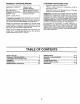
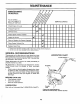
PRODUCT SPECIFICATIONS CUSTOMER RESPONSIBILITIES Read and observe the safety rules. GASOLINE CAPACITY: 3 Quarts (2.8L) Unleaded Regular Follow a regular schedule in maintaining, and using your tiller. OIL (API-SF-SJ): (Capacity: 20 oz./0.
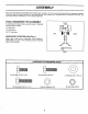
ASSEMBLY Your new tiller has been assembled at the factory with exception of those parts left unassembled for shipping purposes. To ensure safe and proper operation of your tiller all parts and hardware you assemble must be tightened securely. Use the correct tools as necessary to insure proper tightness. TOOLS REQUIRED FOR ASSEMBLY FRONT A socket wrench set will make assembly easier, Standard wrench sizes are listed.
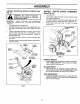
ASSEMBLY UNPACK Fig. 2) CARTON & INSTALL HANDLE (See INSTALL DEPTH (See Fig. 3) STAKE ASSEMBLY Loosen nut "A'. J_lh staples when handling or disposing Be careful of exposed ofAUTION: cartoning material. IMPORTANT: TILLER, BE CABLE(S). Cut cable • Slowly lift and align slot. Insert stake support between engine bracket halves with stake spring down. Bolt stake support to engine brackets with bolts, lock washers and nuts. Tighten securely. Tighten nut "A". Depth stake must move freely.
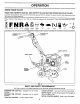
OPERATION KNOW YOUR TILLER READ THIS OWNER'S MANUAL AND SAFETY RULES BEFORE OPERATING YOUR TILLER. Compare the illustrations with your tiller to familiarize yourself with the location of various controls and adjustments. Save this manual for future reference. These symbols ing. rlLUNG FORWARD may appear on your Tiller or in literature supplied with the product.
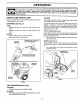
OPERATION I The operation of any tiller can result in foreign objects thrown into the eyes, which can result I in severe eye damage. Always wear safety glasses or eye shields before starting your tiller and while tilling. We recommend a wide vision safety mask for over spectacles or standard safety glasses. I HOW TO USE YOUR TILLER TILLING Know how to operate all controls before adding fuel and oil or attempting to start engine.
OPERATION TO TRANSPORT I _ CAUTION: Before lifting or transporting, allow tiller engine and muffler to cool. Disconnect spark plug wire. Drain gasoline from fuel tank. AROUND THE YARD • • • Wipe off any spilled oil or fuel. Do not store, spill or use gasoline near an open flame. Tip depth stake forward until it is held by the stake spring. Push tiller handles down, raising tines off the ground. Push or pull tiller to desired location.
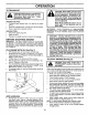
OPERATION NOTE: If at a high altitude (3000 feet) or in cold temperatures (below 32°F), the carburetor fuel mixture may need to be adjusted for best engine performance. See "TO ADJUST CARBURETOR" in the Service and Adjustments section of this manual. NOTE: If engine does not start, see troubleshooting points. Soil conditions are important for proper tilling.Tines will not readily penetrate dry, hard soil which may contribute to excessive bounce and difficult handling of your tiller.
MAINTENANCE MAINTENANCE SCHEDULE FILL IN DATES AS YOU COMPLETE REGULAR SERVICE SERVICE Check Engine Oil Level I_ DATES I_ Change Engine Oil _'1,2 Oil Pivot Points ll_ Inspect Spark Arrester/Muffler Inspect Air Screen Clean or Replace Clean Engine Replace Spark I_ Air Cleaner Cylinder Cartridge 1_2 Fins I_ Plug If 1 - Change more often when operating under a heavy load or in high ambient temperatures. 2 - Service more often when operating in dirty or dusty conditions.
MAINTENANCE Disconnect spark plug wire before performing any maintenance (except carburetor adjustment) to prevent accidental starting of engine. Prevent fires! Keep the engine free of grass, leaves, spilled oil, or fuel. Remove fuel from tank before tipping unit for maintenance. Clean muffler area of all grass, dirt, and debris. Do not touch hot muffler or cylinder fins as contact may cause burns.
MAINTENANCE COOLING SYSTEM MUFFLER (See Fig. 14) Your engine is air cooled. For proper engine performance and long life keep your engine clean. Clean air screen frequently using a stiff-bristledbrush. • Do not operate tiller without muffler. Do not tamper with exhaust system. Damaged mufflers or spark arresters could create a fire hazard. Inspect periodically and replace if necessary. If your engine is equipped with a spark arrester screen assembly, remove every 50 hours for cleaning and inspection.
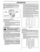
SERVICE AND ADJUSTMENTS I _b AUTION: spark plug wire from spark plug and place wire where it cannot come into contact withDisconnect plug, TILLER TO ADJUST HANDLE HEIGHT I I MID-WIDTH TILLING - 24" PATH (See Fig. 17) Assemble holes "A" in tine hubs to holes "C" in tine shaft. (SEE FIG. 15) Factory assembly has provided lowest handle height. Select handle height best suited for your tilling conditions. Handle height will be different when tiller digs into soil.
SERVICE AND ADJUSTMENTS TINE OPERATION CHECK (See Fig. 19) TO REMOVE BELT GUARD (See Fig. 20) Remove two (2) cap nuts and washers from side of belt guard. Loosen (do not remove) tine shield nut on underside of tine shield. from spark plug to prevent starting WARNING: Disconnect spark plugwhile wire checking line operation.
SERVICE AND ADJUSTMENTS ENGINE FORWARD MOTION (INSIDE) V-BELT ENGINE PULLEY TO ADJUST TRANSMISSION PULLEY BELT GUIDE The carburetor has been preset at the factory and adjustment should not be necessary. However, engine performance can be affected by differences in fuel, temperature, altitude or load.
STORAGE Immediately prepare your tiller for storage at the end of the season or if the unit will not be used for 30 days or more. ENGINE Drain oil (with engine warm) and replace with clean oil. (See "ENGINE" in the Maintenance section of this manual), WARNING: Never store the tiller with gasoline in the tank inside a building where fumes may reach an open flame or spa rk. Allow the engine to cool before storing in any enclosure. CYLINDER(S) Remove spark plug.
TROUBLESHOOTING PROBLEM POINTS AUSE Will not start Hard to start Loss of power 1. Out of fuel. 1. Fill fuel tank 2. 3. 4 5. Engine not "CHOKED" properly. Engine flooded. Dirty air cleaner. Water in fuel. 2. 3. 4. 5. 6. 7. Clogged fuel tank. Loose spark plug wire. 6. See"TO START ENGINE"in the Operation section. Wait several minutes before attempting to start. Clean or replace air cleaner cartridge. Drain fuel tank and carburetor, and refill tank with fresh gasoline.
REPAIR PARTS TILLER - - MODEL NUMBER HANDLE HDF550M ASSEMBLY 1 2 16 3 28 7 8 t'_f" ./ t._j/." KEY NO. 1 2 3 4 5 6 7 8 9 10 11 12 13 PART NO. 180814X428 72140512 9266R 166376 73680500 19111116 19121414 74760516 74760512 10040500 73220500 98000129 180847 DESCRIPTION Panel Pnt Control Bolt, Carriage 5/16-18 UNC x 1-1 ',2 Grip, Handle Handle, L.H. Locknut, Crown 5/16-18 Washer 11/32 x 11/16 x 16"Ga. Washer 3/8 x 7/8 x 14 Ga. Bolt, Hex Hd.
REPAIR PARTS TILLER BELT GUARD AND PULLEY - - MODEL NUMBER HDF550M ASSEMBLY 41 / 1 4 10 42 8 _9 11 12 I 14 15 /" 16 18 KEY NO. 1 2 3 180377 9484R 86777 4 5 6 7 8 9 10 11 12 13 14 15 16 17 18 74610812 73660600 19131316 2009J 180323 74760628 156705X428 19091016 104213X 72140406 133035 2614J 12000028 2649M 151236 PART NO. KEY NO. DESCRIPTION Assembly, Bracket, Belt Guard Clip, Cable Screw, Hex, Washer Hd,, Slotted, Thd.
REPAIR PARTS TILLER - - MODEL NUMBER WHEEL AND DEPTH HDF550M STAKE ASSEMBLY 9 7 6 1 2 10 2 11 22 24 4 7 4 2O 19 18 16 17 KEY NO. 1 2 3 4 5 6 7 8 9 10 11 13 PART NO. 9194R 74760520 74760512 73220500 10040500 73800600 4921H 1952J 122233X 326J 74780628 1951J DESCRIPTION Pin, Clevis Bolt, Hex 5/16-18 x 1-1/4 Bolt, Hex 5/16-18 x 3/4 Nut, Hex 5/16-18 Washer, Lock 5/16 Locknut, w/washer 3/8-16 Clip, Hairpin Support, Depth Stake, R.H.
REPAIR PARTS TILLER - - MODEL NUMBER HDF550M ITNE ASSEMBLY 2 1 2 / 4 2 / 6 6 i 6 KEY NO. 1 2 3 PART NO. 156934 3146R 156932 DESCRIPTION KEY NO. Tine, Outer, R.H. Retainer, Spring Tine, Inner, R.H. 4 5 6 21 PART NO. 156931 156933 4929H DESCRIPTION Tine, Inner, L.H. Tine, Outer, L.H.
REPAIR PARTS TILLER - - MODEL NUMBER HDF550M TRANSMISSION 3 5 11 14 14 lO 14 10 11 12 KEY NO. 1 2 3 5 6 7 8 11 12 PART NO. 74760524 74780652 19131311 73800600 9057R428 165835 1948J 74760544 176112 KEY NO. DESCRIPTION Bolt, Hex 5/16-18 x 1-1/2 Gr. 2 Bolt, Hex, Fin 3/8-16 x 3-1/4 Washer 13/32 x 13/16 x 11 Locknut, Hex, w/washer 3/8-16 Shield, Tine Bracket, Engine, R.H. Bracket, Engine, L.H. Bolt, Hex 5/16-18 x 2-3/4 Transmission 14 15 16 17 18 19 2O PART NO.
REPAIR PARTS TILLER - - MODEL NUMBER HDF550M DECALS 3 9 10 KEY NO. 1 2 3 4 5 6 7 8 9 10 11 --- PART NO. 157377 157380 157378 141914 141907 176391 171077 141906 157381 171078 162215 184860 184861 DESCRIPTION Decal, Logo Decal, Logo Decal, HP, Reverse Decal, Reverse, Tine Control Decal, Hand Placement Decal, Eng. Tiller Decal, OHV. N-I/C Decal, Warning, Rotating Tines Decal, Hvy Duty Decal, Rewind Intek Decal, Tine Shield Wrng.
LIMITED WARRANTY The Manufacturer warrants to the original consumer purchaser that this product as manufactured is free from defects in materials and workmanship. For a period of two (2) years from date of purchase by the original consumer purchaser, we will repair or replace, at our option, without charge for parts or labor incurred in replacing parts, any part which we find to be defective due to materials or workmanship. This Warranty is subject to the following limitations and exclusions. 1. 2. 3. 4.