IMPORTANT MANUAL Do Not Throw Away Poulan 00993-poulan_pro I OWNER'S MANUAL WARNING: MODEL: PDGT26H48B Read the Owner's Manual and follow all Warnings and Safety Instructions. Failure to do so can result in serious injury. LAWN TRACTOR Always Wear Eye Protection During Operation 186714 k_ Rev. 1 06.06.03 JH/TR Printed in U.S.A.
SAFETY RULES SAFE OFERAT,ON PRACT,CES FOR .,DE-ON .OVERS a IMPORTANT: THIS CUTTING MACHINE IS CAPABLEOF AMPUTATINGHANDS AND FEET AND THROWING OBJECTS. FAILURE TO OBSERVE THE FOLLOWING SAFETY INSTRUCTIONS COULD RESULTIN SERIOUS INJURY OR DEATH. I. GENERAL OPERATION • Read, understand, and follow all instructions in the manual and on the machine before starting. • Only allow responsible adults, who are familiar with the instructions, to operate the machine.
SAFETY RULES • • • Be sure the area isclear of other people before mowing. Stop machine if anyone enters the area. Never carry passengers or children even with the blades off. & Do not mow in reverse unless absolutely necessary. Always look down and behind before and while backing. Nevercarry children.They may fall off and be seriously injured or interfere with safe machine operation. Keep children out of the mowing area and underthe watchful care of another responsible adult.
PRODUCT SPECIFICATIONS GasolineCapacity and type: 5.0 Gallons UnleadedRegular Oil Type (API-SF-SJ): SAE 30 (above,32°F) SAE 5W-30 (below32°1=) Oil Capacity: W/Filter: 4.0 Pints W/O Filter: 3.75 Pints Spark Plug: 3ap: .040") Champion QC12YC Ground Speed (MPH): Forward: Reverse: 5.8 2.1 Tire Pressure: Front: Rear: 14 PSI 10 PSI Charging System: 16 AMPS @ 3600 RPM Battery: AMP/HR: 35 MIN. CCA: 280 CASE SIZE: U1R BladeBoltTorque: 45-55 FT.LBS.
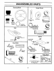
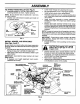
UNASSEMBLED Steering PARTS Wheel Gauge Wheels f © Steering Sleeve (4) Washers 3/8 x 3/4 x 14 Ga.
ASSEMBLY Your new tractor has been assembled at the factory with exception of those parts left unassembled for shipping purposes. To ensure safe and proper operation of your tractor all parts and hardware you assemble must be tightened securely. Use the correct tools as necessary to insure proper tightness. TOOLS REQUIRED FOR ASSEMBLY @1 w A socket wrench set will make assembly easier. Standard wrench sizes are listed.
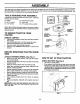
ASSEMBLY • INSTALL SEAT (See Fig. 3) Adjust seat before tightening adjustment knob. • Remove adjustment knob and flat washer securing seat to cardboard packing and set aside for assembly of seat to tractor. Pivot seat upward and remove from the cardboard packing. Remove the cardboard packing and discard. • Place seat on seat pan so head of shoulder bolt is positioned over large slotted hole in pan. • Push down on seat to engage shoulder bolt in slot and pull seat towards rear of tractor.
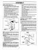
ASSEMBLY TO ATrACH NOSE ROLLER (See Fig. 5) • Assemble brackets "A" and "B"to the inside of mower mounting brackets as shown. Tighten securely. Lower mower linkage with attachment lift control. Be sure belt tension rod is in disengaged position. Install belt into electric clutch pulley groove. Place the suspension arms on outward pointing deck pins. Retain with double loop retainer spring with loops up as shown. NOTE: Be sure bracket tabs are positioned in tab holes in mower brackets.
ASSEMBLY ,/CHECKLIST CHECKTIRE PRESSURE BEFORE YQU OPERATE AND ENJOYYOUR NEW TRACTOR, WE WISH TO ASSURE THAT YOU RECEIVE THE BEST PERFORMANCE AND SATISFACTION FROM THIS QUALITY PRODUCT. The tires on your tractor were overinflated at the factory for shipping purposes. Correct tire pressure is important for best cutting performance. • Reduce tire pressure to PSI shown in "PRODUCT SPECIFICATIONS" section of this manual.
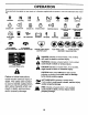
OPERATION These symbols may appear on your tractor or in literature supplied with the product, ing.
OPERATION KNOW YOUR TRACTOR READ THIS OWNER'S MANUAL AND SAFETY RULES BEFORE OPERATING YOUR TRACTOR. Compare the illustrations wtth your tractor to famtlianze yourself with the Iocahon of various controls and adjustments.
T OPERATION The operation of any tractor can result in foreign objects thrown into the eyes, which can result in severe eye damage. Always wear safety glasses or eye shields while operating your tractor or performing any adjustments or repairs. We recommend a wide vision safety mask over spectacles or standard safety glasses.
OPERATION TO ADJUST GAUGE WHEELS (See Fig. 9) UFT LEVER • HIGHEST ,'_" POSIITON Gauge wheels are properly adjusted when they are slightly off the ground when mower is at the desired cutting height in operating position. Gauge wheels then keep the deck in proper position to help prevent scalping in most terrain conditions. NOTE:Adjust gauge wheels with tractor on a flat level surface.
OPERATION CAUTION: Alcohol blended fuels (called gasohol or using ethanol or methanol) can attract moisture which leads to separation and formation of acids during storage. Acidic gas can damage the fuel system of an engine while in storage. To avoid engine problems, the fuel system should be emptied before storage of 30 days or longer. Drain the gas tank, start the engine and let it run until the fuel lines and carburetor are empty. Use fresh fuel next season.
OPERATION • Remove retainer sprmg from the drive belt tenston handle to relieve belt tension. • • Start engme and allow _tto warm up for three (3) minutes • • • Shut-off engine and engage parking brake Engage dnve belt tension handle and replace the retainer spring. • AUTOMATIC TRANSMISSION WARM UP • Before dnving the unit mcold weather, the transmisston should be warmed up as follows: • Be sure the tractor is on level ground. • Place the motion control lever in neutral.
MAINTENANCE FELL IN OATES REGU SERV,CE R S V,CE"DATES Check Brake Operation Check Tire Pressure T Check Operator Presence and Interlock Systems R Check for Loose Fasteners A T Sharpen/Replace Mower Blades Lubrication Chart 0 Check Battery Level R Clean Battery and Terminals _ _ I_s If _3 V e V ° V' Cheek Transaxle Cooling Check V-Belts Check Engine Oil Level V' I_ V # Change Engine Oil (with oil filter) IIP#_,_ E Change Engine Oil (without oil filter) N Clean Air Filter G
MAINTENANCE TRACTOR BLADE Always observe safety rules when performing any maintenance. MANDREL ASSEMBLY CENTER HOLE BRAKE OPERATION If tractor requires more than six (6) feet stopping distance at high speed in highestgear, then brake must be adjusted. (See "TO ADJUST BRAKE"in the Service and Adjustments section of this manual). (SPECIAL) TIRES • Maintain properair pressure in all tires (See"PRODUCT SPECIFICATIONS" section of this manual).
MAINTENANCE TO CLEAN BATI'ERY AND TERMINALS NOTE: Although multi-viscosity oils (5W30, 10W30 etc.) improve starting in cold weather, these multi-viscosity oils will result in irlcreased oil consumption when used above 32°F. Check your engine oil level more frequently to avoid possible engine damage from running low on oil. Corrosion and dirt on the battery and terminals can cause the battery to "leak" power. • Remove terminal guard.
MAINTENANCE CLEAN AIR SCREEN MUFFLER Air screen must be kept free of dirt and chaff to prevent engine damage from overheating. Clean with a wire brush or compressed air to remove dirt and stubborn dried gum fibers. Inspect and'replace corroded muffler and spark attester (if equipped) as it could create a fire hazard and/or damage. CLEAN AIR INTAKE/COOLING SPARK PLUGS AREAS Replace spark plugs at the beginning of each mowing season or after every 100 hours of operation, whichever occurs first.
SERVICE AND ADJUSTMENTS WARNING:TO AVOID SERIOUS INJURY, BEFORE PERFORMING ANY SERVICE OR ADJUSTMENTS: Depress brake pedal fully and set parking brake. Place attachment clutch in "DISENGAGED" position. • Turn ignition key to "STOP" and remove key. • Make sure the blades and all moving parts have completely stopped. • Disconnect spark plug wire from spark plug and place wire where it cannot come in contact with plug. TRACTOR TO REMOVE • • • • • • • • MOWER I CAUTION: Rod is spring loaded.
SERVICE AND ADJUSTMENTS NOTE: To assist in locating hole in flanged pin, the hole in pin is inline with notch on head of pin. If necessary, move mower side-to-side to give space between plate and mower brackets. IMPORTANT: CHECK BELT FOR PROPER ROUTING IN ALL MOWER PULLEY GROOVES. • I& • • • SUSPENSION Engage belt tension rod by pushing rod into locking bracket. UFT LINK loaded. Have a tight grip on rod and CAUTION: Belt tension rod is spring engage slowly. FIG.
SERVICE AND ADJUSTMENTS f MOWER DRIVE BELT INSTALLATION (See Fig. 24) Install belt in both idlers. BOTH FRONT PLATE LINKS MUST BE EQUAL IN LENGTH Install new belt onto electric clutch pulley. • • • Roll belt into upper groove of R.H. mandrel pulley carefully. Carefully check belt routing making sure belt is in the grooves correctly. Reconnect R.H. suspension arm to rear deck bracket with retainer spring. Reassemble R.H. mandrel cover. Engage belt tension rod by pushing rod into locking bracket.
SERVICE AND ADJUSTMENTS TO REPLACE MOWER BLADE (SECONDARY) DRIVE BELT (See Fig. 25) SECONDARY IDLER ARM Park the tractor on level surface. Engage parking brake. Remove mower (See "TO REMOVE MOWER" in this section of manual). • Remove screws from R.H. and L.H. mandrel covers and remove covers. L.H.M_NDREL SPRING IDLER PULLEY SECONDARY SPRING ARM CENTER REMOVE MOWER DRIVE BELT (Refer to "TO REMOVE MOWER DRIVE BELT" illustration in this section of manual). • Carefully roll belt over the top of R.H.
SERVICE AND ADJUSTMENTS TO CHECK AND ADJUST BRAKE TRANSAXLE MOTION NEUTRAL ADJUSTMENT If tractor requires more than five (5) feet to stop at highest speed in highest gear on a level, dry concrete or paved surface, then brake must be checked and adjusted. The motion control lever has been preset at the factory and adjustment should not be necessary. • Park tractor on level surface. Stop tractor by turning ignition key to "OFF" position and engage parking brake.
SERVICE AND ADJUSTMENTS TO REMOVE WHEEL FOR REPAIRS TO ATTACH JUMPER CABLES Connect one end of the RED cable to the POSITIVE (+) terminal of each battery(A-B), taking care not to short against tractor chassis. Connect one end of the BLACK cable to the NEGATIVE (-) terminal (C) of fully charged battery. • Connect the other end of the BLACK cable (D) to good chassis ground, away from fuel tank and battery. FRONT WHEEL (See Fig. 29) • Block up axle securely.
SERVICE AND ADJUSTMENTS TERMINAL ACCESS DOOR TO REMOVE HOOD (See Fig. 32) KEPS NUT HEX BOLT .. -,-.. ASSEMBLY • Raise hood. • Unsnap headlight wire connector. Stand in frontof tractor. Grasp hood at sides, tilt toward engine and lift off of tractor. To replace, reverse above procedures. i POSITIVE AND GRILL • CABLE HOOD TERMINAL GUARD NEGATIVE (SLACK) CABLE HEADLIGHT WIRE CONNECTOR FIG. 31 TO REPLACE • • • • HEADLIGHT BULB Raise hood.
SERVICE AND ADJUSTMENTS ENGINE TO ADJUST THROTTLE CONTROL CABLE (See Fig. 33) The throttle control has been preset at the factory and adjustment should not be necessary. Check adjustment as described below before loosening cable. If adjustment is necessary, proceed as follows: • With engine not running, move throttle control lever to fast position. • Check that swivel is against stop. If it is not, loosen cable clamp screw and pull cable back until swivel is against stop.
STORAGE ENGINE Immediately prepare your tractor for storage at the end of the season or if the tractor will not be used for 30 days or more. A FUEL SYSTEM IMPORTANT:IT ISIMPORTANTTOPREVENTGUM DEPOSITS FROM FORMING IN ESSENTIALFUEL SYSTEM PARTSSUCH AS CARBURETOR, FUEL FILTER, FUEL HOSE, OR TANK DURING STORAGE. ALSO, EXPERIENCE INDICATESTHAT ALCOHOL BLENDED FUELS(CALLEDGASOHOL OR USING ETHANOLOR METHANOL) CANATTRACTMOISTUREWHICH LEADSTOSEPARATIONANDFORMATIONOFACIDSDURING STORAGE.
TROUBLESHOOTING PROBLEM Will not start CAUSE CORRECTION 1. Out of fuel. 1. Fill fuel tank. 2. 3. 4. 5. 6. 7. Engine not =CHOKED" properly. Engine flooded. Bad spark plug. Dirty air filter. Dirty fuel tilter. Water in fuel. 2. 3. 4. 5. 6. 7. See "TO START ENGINE" in Operation section. Wait several minutes before attempting to start. Replace spark plug. Clean/replace air filter. Replace fuel filter. Drain fuel tank and carburetor, refill tank with fresh 8. 9.
TROUBLESHOOTING PROBLEM Engine continues to run when operator leaves seat with attachment clutch POINTS CAUSE 1. Faulty operator-safety 1. 2. CORRECTION presence control system. 1. Check wiring, switches and connections. If not corrected, contact an authohzed service center/ department. Worn, bent or loose blade. Mower deck not level. 1. 2. Replace blade. Tighten blade bolt. Level mower deck. 3. 4. Buildup of grass, leaves, and trash under mower. Bent blade mandrel. 5.
TRACTOR - MODEL SCHEMATIC NUMBER PDGT26H48B; PRODUCT NUMBER 954 56 95-30 A J 11r 16 AMp OC @ 3600 RPM REGULATOR RED _ " 28 VOLTS AC @ 3600 RPM (REGULATOR DISCONNECTED) BROW N i 8LAC K _r eye project. Ir]Sla][ _'i" CH_ RGING l]e_/,.
REPAIR PARTS TRACTOR - MODEL NUMBER PDGT26H48B, PRODUCT NUMBER ELECTRICAL 41 \ 81 33 3O 8 29 I J I I I I 32 954 56 95-30
REPAIR PARTS TRACTOR - MODEL NUMBER PDGT26H48B, PRODUCT NUMBER ELECTRICAL KEY NO. 1 2 8 10 11 12 16 21 22 24 25 26 27 28 29 3() 33 40 41 42 43 45 46 50 79 81 89 PART NO. 144927 74760412 7603J 145211 150109 145769 176138 175688 4152J 185464 146149 108824X 73510400 170697 160784 175566 140401 170238 17720408 131563 178861 122822X 169635 174653 175242 109748X 169639 DESCRIPTION Battery Bolt Hex Head 1/4-20 x 3/4 Tray, Battery Bolt Btr Frt 1/4-20 x 7.
REPAIR PARTS TRACTOR CHASSIS " - MODEL NUMBER PDGT26H48B, AND ENCLOSURES 161 158 37 138 47 58 28 17 21 ;11 i = !_2 56 '_l o 19 99 86 34 PRODUCT NUMBER 954 56 95-30
REPAIR PARTS TRACTOR CHASSIS KEY NO. 1 2 5 6 7 8 14 16 17 18 19 20 21 24 28 30 31 32 33 34 35 36 37 39 43 44 45 47 50 56 58 - MODEL NUMBER ......... PDGT26H48B, PRODUCT NUMBER 954 56 95-30 AND ENCLOSURES PART NO. 180375 175282 163976X428 157882 17720408 184668 175260X428 121794X 17060612 175289X428 19131312 74780616 73800600 179717X428 179716X428 145052 161419 161327 161326 177018 19111116 17060512 178510X428 175278 136939 136940 176018 17490608 175476 176016 183569 KEY NO.
REPAIR PARTS ....
REPAIR PARTS TRACTOR GROUND PART NO. 1 ....... 50 52 55 56 58 61 64 65 68 69 70 73 74 PDGT26H48B, PRODUCT NUMBER 954 56 95-30 DRIVE KEY NO. 2 3 6 7 9 20 22 23 29 33 34 35 36 37 38 39 40 41 42 46 48 "- MODEL NUMBER DESCRIPTION Transaxle Hydro Gear 331-3000 (Order Parts From Transaxle Manufacturer) 7070E Key Sq. 1/4 x 2.
REPAIR PARTS TRACTOR STEERING - MODEL NUMBER PDGT26H48B, PRODUCT ASSEMBLY ,.. _3 23 22 15 .
REPAIR PARTS TRACTOR - MODEL NUMBER PDGT26H48B, PRODUCT NUMBER STEERING ASSEMBLY KEY NO. PART NO.
REPAIR PARTS TRACTOR - MODEL NUMBER PDGT26H48B, PRODUCT NUMBER 954 56 95-30 ENGINE B4 _/74 I 84 81 18 15 37 29 26 "37 / ! 39 I SPARK ARRESTER engine-intek-FLS_l KEY NO. 2 8 9 10 11 12 15 18 20 21 22 24 25 26 27 28 29 31 PART NO. 149723 121361X 177748 175287 179335 143996 179115 179124X428 175437X428 171875 175440X428 11050600 73920600 3645J 139277 7834R 137180 145006 DESCRIPTION Engine Briggs, Model No. 446777 (Older p_fts fz'om engine manuf.) Muffler Side Pulley V-Idler Keeper Asm.
REPAIR PARTS TRACTOR - MODEL NUMBER PDGT26H48B, PRODUCT NUMBER 954 56 95-30 LIFT ASSEMBLY 40 43 35 73 31 t0 8 10 / 2 6 23 7O 7O 76 ° 26 4 78 2_ II KEY NO. 1 2 3 4 5 6 7 8 10 11 12 23 24 26 29 30 31 32 33 PART NO. 121006X 180045 159189 12000022 19292016 71110624 175830 175831X421 183894 175375 163552 4939M 73350800 73680800 150233 110807X 19131016 137150 76020308 ROO ,'-_&li;., _-_vel Shaft Asm., Lift Vgt Lever Asm., L!t _' E-Ring Truarc _' : -87 Washer 29/32 x 1-1/4 x 16 Ga.
REPAIR PARTS TRACTOR - MODEL NUMBER PDGT26H48B, PRODUCT NUMBER 954 56 95-30 'SEAT ASSEMBLY seatS-vgt _KEY NO, 1 2 4 5 ,6 7 8 10 12 13 14 75 PART NO. 171684 140551 127018X 145006 73800600 124181X 171877 182493 121246X 121248X 72050412 121249X KEY NO. DESCRIPTION Seat Bracket, Pivot Seat Bolt, Shoulder 5/16-18 x .62 Clip, Push-In Hinged Nut, Crownlock 3/8-16 Spring, Seat Cprsn.
REPAIR PARTS TRACTOR - MODEL NUMBER PDGT26H48B, PRODUCT NUMBER 954 56 95-30 DECALS 3 9 5 5 15 \ 4 10 6 7 29 2 ...... , 17 2 14 KEY NO. PART NO. DESCRIPTION KEY NO, PART NO, DESCRIPTION 1 2 3 4 5 6 7 8 9 10 11 164097 184858 176272 176273 185539 170563 166960 178502 172740 157140 181253 Decal, Dash Decal, Engine Decal, Hood, RH Decal, Hood, LH Decal, Hood Sides Decal, Warning Decal, Bypass Decal, Deck Caution Decal Decal, Danger Ft.
REPAIR PARTS • + TRACTOR MOWER - MODEL NUMBER PDGT26H48B, PRODUCT NUMBER 954 56 95-30 DECK 46 132 95 46 33 45 _30 112 I I 121 i 47 21 114 110 '1 5 I,! mower_dec_.4.
REPAIR PARTS TRACTOR ; MODEL NUMBER MOWER KEY NO. PART NO. 1 3 5 6 8 180358X421 178915 4939M 178024 174365 11 173921 180054 13 14 15 16 17 18 19 20 21 24 25 26 27 28 29 30 31 32 33 36 37 39 42 43 45 46 47 48 PDGT26H48B, PRODUCT NUMBER954 56 95-30 DECK 174360 174358 110485X 174493 72110610 72140505 132827 174378 73680500 105304X 178102 110452X 180655X428 19111016 131491 173984 129963 177865 178342 19131316 177968 174375 122052X _74373 180806 137729 180808 174368 KEY NO.
LIMITED WARRANTY The Manufacturerwarrantsto the originalconsumer purchaserthat this product as manufacturedisfree from defectsin materials and workmanship.For a periodoftwo (2) years from date of purchaseby the originalconsumerpurchaser,we wiltrepairor replace, at our option,withoutchargefor parts or labor incurredin replacingparts, any part whichwe find to be defective due to materialsor workmanship.ThisWarrantyis subjectto the following limitationsand exclusions. 1.
SUGGESTED GUIDE FOR SIGHTING SLOPES FOR SAFE OPERATION 15 DEGREES down the face of slopes, never across the face. Do not mow ARNING: To avoid serious injury, operate your tractor up and slopes greater than 15 degrees. Make turns gradually to prevent tipping or loss of control. Exercise extreme caution when changing direction on slopes. _t D MAX. q 1. F(J_t this page along dotted line indicated above. 2.
PARTS AND SERVICE Your POULAN PRO product has been expertly engineered and carefully manufactured to rigid quality standards. As with all mechanical products, some adjustments or part replacement may be necessary during the life of your unit. FOR SERVICE OR REPLACEMENT PARTS: 1. Consult your dealer/place of purchase. 2.