IMPORTANT MANUAL Do Not Throw Away OWNER'S MANUAL MODEL NUMBER: PP208EPS24L SNOW THROWER WARNING: Read the Owner's Manual and follow all Warnings and Safety Instructions. Failure to do so can result in serious injury. Always Wear Eye Protection During Operation 440575 11.09.10 TH Printed in U.S.A.
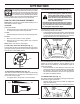
IMPORTANT Safe Operation Practices for Walk-Behind Snow Throwers This snow thrower is capable of amputating hands and feet and throwing objects. Failure to observe the following safety instructions could result in serious injury. WARNING: Snow throwers have exposed rotating parts, which can cause severe injury from contact, or from material thrown from the discharge chute. Keep the area of operation clear of all persons, small children and pets at all times including startup.
6. When cleaning, repairing or inspecting the snow thrower, stop the engine and make certain the collector/impeller and all moving parts have stopped. Disconnect the spark plug wire and keep the wire away from the plug to prevent someone from accidentally starting the engine. 7. Do not run the engine indoors, except when starting the engine and for transporting the snow thrower in or out of the building. Open the outside doors; exhaust fumes are dangerous. 8.
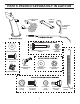
PARTS PACKED SEPARATELY IN CARTON (1) POWER CORD (198563) (1) MULTIWRENCH (180684) (3) RETAINER SPRINGS (169675) (2) SHEAR BOLTS 1/4-20 x 1-3/4 (192090) (2) FLAT WASHERS (2) LOCKNUTS 1/4-20 (73800400) (2) CARRIAGE BOLTS 3/8-16 x 2.
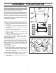
ASSEMBLY / PRE-OPERATION Read these instructions and this manual in its entirety before you attempt to assemble or operate your new snow thrower. Reading the entire manual will familiarize you with the unit, which will assist you in assembly, operation and maintenance of the product. Your new snow thrower has been assembled at the factory with the exception of those parts left unassembled for shipping purposes. All parts such as nuts, washers, bolts, etc.
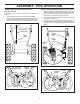
ASSEMBLY / PRE-OPERATION INSTALL AUGER CONTROL ROD (See Figs. 5 and 6) 1. Retrieve vinyl sleeve and spring from bag of parts and retrieve the auger control rod from carton chute tray. Slide straight rod end through the small hole in the vinyl sleeve. Hook spring in hole in rod end. 2. Hook end of spring into control arm with loop opening up as shown. (See Fig. 5) 3. With top end of rod positioned under right side of control panel, push down on rod and insert end of rod into hole in auger control bracket.
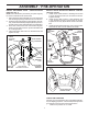
ASSEMBLY / PRE-OPERATION INSTALL DISCHARGE CHUTE / CHUTE ROTATOR HEAD (See Fig. 7) NOTE: The multi-wrench provided in your parts bag may be used to install the chute rotator head. 1. Place discharge chute assembly on top of chute base with discharge opening toward front of snow thrower. 2. Position chute rotator head over chute bracket. If necessary, rotate chute assembly to align square and pin on underside of chute rotator head with holes in chute bracket. 3.
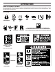
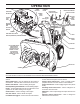
OPERATION KNOW YOUR SNOW THROWER READ THIS OWNER'S MANUAL AND ALL SAFETY RULES BEFORE OPERATING YOUR SNOW THROWER. Compare the illustrations with your snow thrower to familiarize yourself with the location of various controls and adjustments. Save this manual for future reference. These symbols may appear on your snow thrower or in literature supplied with the product. Learn and understand their meaning.
OPERATION ELECTRIC START BUTTON MUFFLER GASOLINE FILLER CAP AUGER CONTROL LEVER POWER CORD PLUG CHOKE CONTROL DISCHARGE CHUTE CONTROL LEVER DRIVE SPEED CONTROL LEVER CHUTE DEFLECTOR SAFETY IGNITION KEY DEFLECTOR REMOTE CONTROL LEVER TRACTION DRIVE CONTROL LEVER LH TURN TRIGGER ON / OFF SWITCH DISCHARGE CHUTE PRIMER FUEL SHUT-OFF VALVE LIGHT RECOIL (AUXILIARY) STARTER HANDLE CLEAN-OUT TOOL HANDLE KNOB MUFFLER NOTE: ITEMS ABOVE ARE SHOWN IN THEIR TYPICAL LOCATION ON THE ENGINE.
OPERATION The operation of any snow thrower can result in foreign objects thrown into the eyes, which can result in severe eye damage. Always wear safety glasses or eye shields while operating your snow thrower or performing any adjustments or repairs. We recommend standard safety glasses or a wide vision safety mask worn over spectacles. TO CONTROL SNOW DISCHARGE (See Fig.
OPERATION USING THE CLEAN-OUT TOOL (See Fig. 15) In certain snow conditions, the discharge chute may become clogged with ice and snow. Use the clean-out tool to dislodge this blockage. • Slower speeds are for heavier snow and faster speeds are for light snow and transporting the snow thrower. It is recommended that you use a slower speed until you are familiar with the operation of the snow thrower.
OPERATION TO ADJUST SKID PLATES (See Fig. 17) NOTE: The wrench provided in your parts bag may be used to adjust the skid plates. Skid plates are located on each side of the auger housing and adjust the clearance between the scraper bar and the ground surface. Adjust skid plates evenly to proper height for current surface conditions.
OPERATION TO START ENGINE • Be sure fuel shut-off valve is in the “OPEN” position. Your snow thrower engine is equipped with both a 120 Volt A.C. electric starter and a recoil starter. The electric starter is equipped with a three-wire power cord and plug and is designed to operate on 120 Volt A.C. household current. • Be sure your house is a 120 Volt A.C. three-wire grounded system. If you are uncertain, consult a licensed electrician. 5. Pull recoil starter handle quickly.
MAINTENANCE GENERAL RECOMMENDATIONS The warranty on this snow thrower does not cover items that have been subjected to operator abuse or negligence. To receive full value from the warranty, operator must maintain snow thrower as instructed in this manual. Some adjustments will need to be made periodically to properly maintain your snow thrower. All adjustments in the Service and Adjustments section of this manual should be checked at least once each season.
MAINTENANCE • Oil will drain more freely when warm. • Catch oil in a suitable container. NOTE: The left side wheel may be removed from snow thrower for easier access to the oil drain plug and placement of a suitable container. The unit tilted, resting on the frame with the left wheel removed, will help drain any oil trapped inside the engine. (See “TO REMOVE WHEELS” in the Service and Adjustments section of this manual). 1. Remove safety ignition key and disconnect spark plug wire from spark plug.
SERVICE AND ADJUSTMENTS IMPELLER SHEAR BOLTS The impeller is secured to the impeller shaft with two (2) capscrew/shear bolts and hex nuts. Should a foreign object or ice become lodged in the impeller, the capscrews are designed to break, preventing damage to any other components. If impeller does not turn when auger control lever is engaged, check to see if the capscrews have sheared. To replace the capscrew/shear bolts: 1. Disengage all controls and move throttle control to STOP position.
SERVICE AND ADJUSTMENTS TO REPLACE BELTS (See Fig. 22) The auger and traction drive belts are not adjustable. If the belts are damaged or begin to slip from wear, they should be replaced. It is recommended that the belt(s) be replaced by a service center/department. NOTE: It is recommended that both the auger and traction drive belt be replaced at the same time.
SERVICE AND ADJUSTMENTS ENGINE TO REMOVE WHEELS (See Fig. 23) • Remove the klik pin and remove wheel from axle. IMPORTANT: When installing wheel, be sure to use the axle hole closest to the end of the shaft – do not use the hole in the wheel hub (if equipped). Inner hole in axle and hole in wheel hub are not used for your model snow thrower. NOTE: To seal punctures or prevent flat tires due to slow leaks, tire sealant may be purchased from your local parts dealer.
STORAGE Immediately prepare your unit for storage at the end of the season or if the unit will not be used for 30 days or more. • Empty the fuel tank by starting the engine and letting it run until the fuel lines and carburetor are empty. • Never use engine or carburetor cleaner products in the fuel tank or permanent damage may occur. • Use fresh fuel next season. NOTE: Fuel stabilizer is an acceptable alternative in minimizing the formation of fuel gum deposits during storage.
TROUBLESHOOTING See appropriate section in manual unless directed to an authorized service center/department. PROBLEM Does not start CAUSE 1. Fuel shut-off valve (if so equipped) in OFF position. 2. Safety ignition key is not inserted. 3. Out of fuel. 4. Throttle in STOP position (or ON/OFF switch is OFF). 5. Choke in OFF position. 6. Primer not depressed. 7. Engine is flooded. 8. Spark plug wire is disconnected. 9. Bad spark plug. 10. Stale fuel. 11. Water in fuel. CORRECTION 1.
REPAIR PARTS SNOW THROWER - MODEL PP208EPS24L (96198003800) AUGER HOUSING / IMPELLER ASSEMBLY 1 KEY NO. 1 2 3 4 PART NO. 404928X428 404931X431 72270505 155377 DESCRIPTION AUGER HOUSING SCRAPER BAR CARRIAGE BOLT 5/16−18 X .625 NUT 5/16−18 3 (5x) 4 (5x) 2 01.07.001-A 2 3 1 1 2 3 01.07.024-B KEY NO. PART NO. DESCRIPTION 1 2 3 420478 411939 179582 AUGER BEARING BEARING PLUG SCREW 5/16−18 X 1.00 NOTE: All component dimensions given in U.S. inches. 1 inch = 25.
REPAIR PARTS SNOW THROWER - MODEL PP208EPS24L (96198003800) AUGER HOUSING / IMPELLER ASSEMBLY 5 11 11 6 7 15 14 16 11 12 4 13 11 3 8 12 17 10 1 37 9 2 9 33 37 32 34 31 9 30 31 26 29 36 27 28 23 22 21 20 25 35 22 23 24 21 18 2 (EXPLODED) 19 01.07.026-D NOTE: All component dimensions given in U.S. inches. 1 inch = 25.4 mm IMPORTANT: Use only Original Equipment Manufacturer (O.E.M.) replacement parts.
REPAIR PARTS SNOW THROWER - MODEL PP208EPS24L (96198003800) AUGER HOUSING / IMPELLER ASSEMBLY KEY NO. 1 2 3 4 5 6 7 8 9 10 11 12 13 14 15 16 17 18 19 20 21 22 23 24 25 26 27 28 29 30 31 32 33 34 35 36 37 PART NO.
REPAIR PARTS SNOW THROWER - MODEL PP208EPS24L (96198003800) AUGER HOUSING / IMPELLER ASSEMBLY 2 1 KEY NO. PART NO. DESCRIPTION 1 2 420493X421 420494X421 AUGER ASSEMBLY LH 24 AUGER ASSEMBLY RH 24 01.07.017-A 2 1 3 1 2 01.11.003-B 3 KEY NO. PART NO. 1 2 435951 426589 3 72110510 DESCRIPTION PLATE SKID PLASTIC HDPE NUT 5/16-18 LARGE HEX FLANGE BLK CARRIAGE BOLT 5/16-18 X 1.25 NOTE: All component dimensions given in U.S. inches. 1 inch = 25.
REPAIR PARTS SNOW THROWER - MODEL PP208EPS24L (96198003800) CONTROL PANEL / DISCHARGE CHUTE 5 7 15 3 16 *14 *11 2 *10 6 4 6 KEY NO. PART NO. DESCRIPTION 1 2 3 4 5 6 7 8 9 *10 *11 *12 *13 *14 15 16 435023X428 178633X428 420673 420325 414280 128415 17501010 430324 419822X431 179829 191730 72250505 751153 184505 420679 420672 1 CHUTE WELDMENT DEFLECTOR WELDMENT DEFLECTOR CONTROL ASSEMBLY DEFLECTOR SEAL KNOB BLACK POP RIVET 6 SCREW 10-24 X .
REPAIR PARTS SNOW THROWER - MODEL PP208EPS24L (96198003800) CONTROL PANEL / DISCHARGE CHUTE 2 2 1 *3 *7 *6 *4 KEY NO. 1 2 *3 *4 *5 *6 *7 PART NO. 428272 17501010 420678 405932 420675 428273 428310 *5 01.09.010-B DESCRIPTION LEVER/CABLE ROTATOR ASSEMBLY SCREW 10-24 X .625 ROTATOR HEAD ROTATOR PIVOT BRACKET PULLEY PIVOT CABLE ASSEMBLY ADJUSTABLE CABLE ASSEMBLY HEAT SHIELD NOTES: 1. ITEMS INDICATED WITH AN * ARE LISTED AS REFERENCE FOR SERVICE PARTS ONLY. 2 1 KEY NO. PART NO.
REPAIR PARTS HANDLES SNOW THROWER - MODEL PP208EPS24L (96198003800) 7 4 5 3 2 6 4 5 1 KEY NO. 1 2 3 4 5 6 7 PART NO. 182906 178668 180927 184471 175262 178770 183784 DESCRIPTION CONSOLE PANEL HEADLIGHT BEZEL FLOOD HEADLIGHT SHOULDER SCREW 10−24 X .625 SCREW 10−24 X 1.25 WIRE HARNESS BULB KEY NO. 1 2 3 4 5 6 PART NO. 412675X431 414572 178831 169675 17060410 421252X431 DESCRIPTION INTERLOCK SPRING INTERLOCK CAM TORSION SPRING RETAINER SCREW 1/4−20 X .625 INTERLOCK STOP 01.10.
REPAIR PARTS HANDLES SNOW THROWER - MODEL PP208EPS24L (96198003800) 3 3 4 4 4 1 3 KEY NO. PART NO. DESCRIPTION 1 2 3 4 419798X431 419799X431 74780524 751153 LOOP HANDLE LH LOOP HANDLE RH SCREW 5/16−18 X 1.50 NUT 5/16−18 KEY NO. PART NO. DESCRIPTION 1 2 3 4 419797X431 427513X431 428867 17000616 LOWER HANDLE PIVOT SUPPORT WELDMENT SCREW 5/16−18 X .750 SCREW 3/8−16 X 1.00 4 3 2 01.08.004-B 1 2 4 3 4 4 3 4 01-05-013-A NOTE: All component dimensions given in U.S. inches. 1 inch = 25.
SNOW THROWER - MODEL PP208EPS24L (96198003800) REPAIR PARTS HANDLES 10 2 11 8 6 7 5 4 7 9 9 1 3 13 8 12 13 14 14 12 KEY NO. 1 2 3 4 5 6 7 8 9 10 11 12 13 14 PART NO. 412683X431 424517X431 424516X431 412679X008 426918X008 412677 421613 169675 17060410 414280 414281 178899 19131316 72120618 01.08.002-G DESCRIPTION CONTROL PANEL CONTROL LEVER LH CONTROL LEVER RH TRACTION ROD ARM IMPELLER ROD ARM INTERLOCK BAIL SPACER RETAINER SCREW 1/4-20 X .
SNOW THROWER - MODEL PP208EPS24L (96198003800) REPAIR PARTS HANDLES 2 10 KEY NO. 1 2 3 4 5 6 7 8 9 10 10 3 1 8 9 PART NO. 180480 405740 180445 187716 180447 178669 180926 72270505 155377 169675 DESCRIPTION IMPELLER ROD ASSEMBLY TRACTION ROD ASSEMBLY SHIFTER ROD TOP SHIFTER ROD BOTTOM SPRING SLEEVE IMPELLER SPRING TRACTION SPRING CARRIAGE BOLT 5/16-18 X .75 NUT 5/16-18 RETAINER 4 5 7 10 5 6 01.12.001-E NOTE: All component dimensions given in U.S. inches. 1 inch = 25.
SNOW THROWER - MODEL PP208EPS24L (96198003800) REPAIR PARTS DRIVE 6 7 8 3 1a 2 3 4 6 4 1b 7 5 1b 01.03.002-A KEY NO. PART NO. DESCRIPTION 1 1a 1b 2 3 4 5 6 7 8 404923 404307 184206 402691 174697 179830 146315 17490508 155443 189282 AXLE ASSEMBLY (assy of 1a,1b) AXLE SHAFT ROLL PIN 3/16 X 1.50 SPROCKET THRUST WASHER BEARING SCREW 5/16−18 X .625 SCREW 5/16−18 X .500 KLIK PIN 1/4 X 1.50 SQUARE KEY NOTE: All component dimensions given in U.S. inches. 1 inch = 25.
SNOW THROWER - MODEL PP208EPS24L (96198003800) REPAIR PARTS DRIVE 42 EXPLODED 46 2 45 16 48 17 1 18 15 11 9 9 10 8 7 12 9 11 53 13 14 47 15 49 20 22 19 53 11 4 34 53 23 52 21 6 24 5 33 23 53 3 28 26 29 30 31 33 32 35 27 24 26 38 53 36 37 4 23 50 24 24 25 53 42 43 39 44 41 40 39 01.02.013-A NOTE: All component dimensions given in U.S. inches. 1 inch = 25.4 mm IMPORTANT: Use only Original Equipment Manufacturer (O.E.M.) replacement parts.
REPAIR PARTS DRIVE KEY NO. PART NO. 1 198875 2 3 4 5 6 7 8 9 10 11 12 13 14 15 16 17 18 19 20 21 22 23 24 25 26 17501010 402685X428 17490508 57079 405485 198580 403097X008 402881 403096X431 191730 402856X008 416717X431 187101 700279 427542 402568 169675 401732 402310 12000036 402878 751153 408981 73930500 198176X431 SNOW THROWER - MODEL PP208EPS24L (96198003800) DESCRIPTION KEY NO. PART NO. DESCRIPTION SPEED SELECTOR ASSEMBLY SCREW 10-24 X .625 END PLATE SCREW 5/16-18 X .
REPAIR PARTS SNOW THROWER - MODEL PP208EPS24L (96198003800) CHASSIS / ENGINE / PULLEYS 2 3 2 3 1 01.00.034-A KEY NO. PART NO. DESCRIPTION -1 2 3 436266 418694X428 150406 428867 COMPLETE LCT ENGINE FRAME BOLT 3/8-16 SCREW 5/16-18 X .750 KEY NO. PART NO. DESCRIPTION 1 427963X428 ENGINE MOUNTING PLATE KEY NO. PART NO. DESCRIPTION 1 428684 COVER ASSEMBLY 1 01.01.004-A 1 01.21.013-B NOTE: All component dimensions given in U.S. inches. 1 inch = 25.
REPAIR PARTS SNOW THROWER - MODEL PP208EPS24L (96198003800) CHASSIS / ENGINE / PULLEYS 23 22 24 14 21 20 11 19 14 21 20 13 18 17 12 14 15 16 6 7 10 8 4 3 5 9 1 2 01.21.003-C KEY NO. PART NO. DESCRIPTION KEY NO. PART NO. DESCRIPTION 1 2 3 4 5 6 7 8 9 10 11 12 408007 419744 423723 180523 426589 74780524 423990X431 428867 424297 751153 187786 180522 IMPELLER BELT TRACTION BELT IDLER ARM BRACKET IDLER PULLEY NUT 5/16-18 SCREW 5/16-18 X 1 .50 IDLER BRACKET SCREW 5/16-18 X .
REPAIR PARTS WHEELS SNOW THROWER - MODEL PP208EPS24L (96198003800) 2 17 20 16 18 15 24 17 16 20 19 2 3 4 2 1 5 6 23 22 7 01.15.001-B 8 9 7 22 10 11 21 21 11 10 4 23 19 14 12 KEY NO. 1 2 3 4 5 6 7 8 9 10 11 12 13 14 15 16 17 18 19 20 21 22 23 24 13 13 14 9 6 3 5 8 12 PART NO.
REPAIR PARTS WHEELS SNOW THROWER - MODEL PP208EPS24L (96198003800) 1 2 KEY NO. PART NO. DESCRIPTION 1 2 432337X421 432338X431 WHEEL ASSEMBLY LH WHEEL ASSEMBLY RH PART NO. 410293 410294 17490408 17600406 DESCRIPTION CABLE BRACKET LH CABLE BRACKET RH SCREW 1/4-20 X .500 SCREW 1/4-20 X .375 01.06.015-A 4 2 KEY NO. 1 2 3 3 4 1 01.15.003-C NOTE: All component dimensions given in U.S. inches. 1 inch = 25.4 mm IMPORTANT: Use only Original Equipment Manufacturer (O.E.M.) replacement parts.
SNOW THROWER - MODEL PP208EPS24L (96198003800) REPAIR PARTS BAG OF PARTS 4 6 5 8 7 3 9 10 2 12 1 11 01.14.003-B 1 KEY NO. PART NO. DESCRIPTION 1 2 3 4 5 6 7 8 9 10 11 12 198563 169675 180684X008 184505 179829 191730 72250505 751153 73800600 19131316 192090 73800400 POWER CORD RETAINER PIN WRENCH REMOTE SPRING SHOULDER BOLT 1/4-20 LOCKNUT 1/4-20 CARRIAGE BOLT 5/16-18 X 5/8 LOCKNUT 5/16-18 LOCKNUT 3/8-16 WASHER 3/8 SHEAR BOLT 1/4-20 X 1-13/16 LOCKNUT 1/4-20 KEY NO. PART NO.
REPAIR PARTS DECALS SNOW THROWER - MODEL PP208EPS24L (96198003800) 1 9 2 6 3 7 1 KEY NO. PART NO. DESCRIPTION 1 2 3 6 7 9 --- 181037 181042 181035 181033 429590 429591 440575 440576 DECAL, DANGER DECAL, DANGER DECAL, DANGER, DEFLECTOR DECAL, INSTRUCTION DECAL, CONSOLE, LT SPD/LEV/PWRST DECAL, CONSOLE, RT SPD/LEV/PWRST OWNER’S MANUAL, ENGLISH OWNER’S MANUAL, FRENCH NOTE: All component dimensions given in U.S. inches. 1 inch = 25.4 mm IMPORTANT: Use only Original Equipment Manufacturer (O.E.M.
LIMITED WARRANTY The Manufacturer warrants to the original consumer purchaser that this product as manufactured is free from defects in materials and workmanship. For a period of two (2) years from date of purchase by the original consumer purchaser, we will repair or replace, at our option, without charge for parts or labor incurred in replacing parts, any part which we find to be defective due to materials or workmanship. This Warranty is subject to the following limitations and exclusions. 1.