IMPORTANT MANUAL Do Not Throw Away Poulan WARNING: OWNER'S MANUAL Read the Owner's Manual and follow all Warnings and Safety Instructions. Failure to do so can result in serious injury. MODEL: PR1842STD LAWN TRACTOR 183748 Always Wear Eye Protection During Operation 5.2.02 TR Printed in U.S.A.
SAFETY RULES SAFE OPERATION PRACTICES FOR RIDE-ON MOWERS & IMPORTANT: THIS CUTTING MACHINE IS CAPABLE OF AMPUTATING HANDS AND FEET AND THROWING OBJECTS. FAILURE TO OBSERVE THE FOLLOWING SAFETY INSTRUCTIONS COULD RESULT IN SERIOUS INJURY OR DEATH. I. GENERAL • • • • • • • • • • • • OPERATION Avoid starting or stopping on a slope. If tires lose traction, disengage the blades and proceed slowly straight down the slope.
SAFETY RULES & Safe Operation Practices for Ride-On Mowers & • Be sure the area is clear of other people before mowing. Stop machine if anyone enters the area. Never carry passengers orchildren even with the blades off. Look for this symbol to point out important safety precautions. It means CAUTION!!! BECOMEALERT!!! YOUR SAFETY IS INVOLVED. • Do not mow in reverse unless absolutely necessary. Always look down and behind before and while backing. Never carry children.
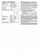
PRODUCT SPECIFICATIONS GASOLINE CAPACITY &ND TYPE: 2.00 GALLONS UNLEADED REGULAR OILTYPE(API-SF-SJ): SAE 30 (above 32°F) SAE 5W-30 (below 32°F) SPARK PLUG: CHAMPION RCt2YC CONGRATULATIONS on yourpurchaseofanewtractor. It has been designed, engineered and manufactured to give you the best possible dependability and performance. Should you experience any problem you cannot easily remedy, please contact your nearest authorized service center/department.
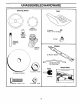
UNASSEMBLED Steering HARDWARE Wheel Seat Q Steering Wheel Insert (1) Washer 17/32 x 1-3/16 x 12 Gauge Steering Wheel Adapter (1) Knob Steering Extension Shaft Steering Sleeve (2) Mulcher O @ (1) Locknut (1) Hex Bolt 1/4-28 x 1-1/4 (1) Locknut Slope Sheet Keys 1/2-20 (2) Keys 1/4-28 5 _"'____ For Future Use (1) Large Flat Washer ® Blades
ASSEMBLY Your new tractor has been assembled at the factory with exception of those parts left unassembled for shipping pu rposes. To ensure safe and proper operation of your tractor all parts and hardware you assemble must be tightened securely. Use the correct tools as necessary to insure proper tightness. TOOLS REQUIRED FOR ASSEMBLY A socket wrench set will make assembly easier. Standard wrench sizes are listed.
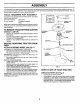
ASSEMBLY NOTE: You may now roll or drive your tractor off the skid. Follow the appropriate instruction below to remove the tractor from the skid. TO ROLL TRACTOR OFF SKID (See Operation section, page 10, for location and function of controls) • • • FIG. 2 INSTALL SEAT (See Fig. 3) • • • • • Remove banding holding deflector shield up aga!nst tractor. TO DRIVE TRACTOR OFF SKID (See Operation section, page 10, for location and function of controls) Adjust seat before tightening adjustment knob.
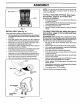
ASSEMBLY CHECK IMPORTANT: FOR SHIPPING PURPOSES, THE MULCHER PLATE WAS PREATTACHED TO YOUR MOWER. THE MULCHER PLATE MUST ONLY BE USED WITH THE MULCHING BLADES THAT CAME PACKED SEPARATELY IN THE CARTON. • MOWER FOR CHECK MULCHER PLATE DECK LEVELNESS For best cutting results, mower housing should be properly leveled. See"TO LEVEL MOWER HOUSING" in the Service and Adjustments section of this manual.
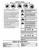
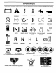
OPERATION These symbols may appear on your tractor or in literature supplied with the product. Learn and understand their meaning.
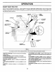
OPERATION KNOW YOUR TRACTOR READ THIS OWNER'S MANUAL AND SAFETY RULES BEFORE OPERATING YOUR TRACTOR Compare the illustrations with your tractor to familiarize yourself with the locations of various controls and adjustments. Save this manual for future reference, IGNITION SWITCH ATTACHMENT CLUTCH LEVER LIGHT POSITION AMMETER LIFT LEVER PLUNGER CHOKE CONTROL_ LIFT LEVER CLUTCH/BRAKE THROTTLE CONTROL GEARSHIFT LEVER PARKING BRAKE LEVER FIG.
OPERATION The operation of any tractor can result in foreign objects thrown into the eyes, which can result in severe eye damage. Always wear safety glasses or eye shields while operating your tractor or performing any adjustments or repairs. We recommend a wide vision safety mask over spectacles or standard safety glasses. HOW TO USE YOUR TRACTOR TO SET PARKING BRAKE CAUTION: Always stop tractor completely, as described above, before leaving the operator's position; to empty grass catcher, etc.
OPERATION TO ADJUST GAUGE WHEELS (See Fig. 7) "ENGAGED" Gauge wheels are properly adjusted when they are slightty off the ground when mower is at the desired cutting height in operating position. Gauge wheels then keep the deck in proper position to help prevent scalping in most terrain conditions. LIFT LEVER HIGH POSITION ''_ NOTE:Adjust gauge wheels with tractor on a flat level surface.
OPERATION BEFORE CHECK STARTING ENGINE THE ENGINE TO START • NOTE: Before starting, read the warm and cold star{inn procedures below. • Insert key into ignition and turn key clockwise to "START" position and release key as soon as engine starts. Do not run starter continuously for more than fifteen seconds per minute. If the engine does not start after several attempts, push chokecontrol in, waita few minutes and try again. If engine still does not start, pull the choke control out and retry.
OPERATION MOWING • • • • • • TIPS MULCHING MOWING TIPS IMPORTANT: FOR BEST PERFORMANCE, KEEP MOWER HOUSING FREE OF BUILT-UP GRASS AND TRASH. CLEAN AFTER EACH USE. Mower should be properly leveled for best mowing performance. See "TO LEVEL MOWER HOUSING" in the Service and Adjustments section of this manual. The left hand side of mower should be used for trimming. Drive sothat clippings are discharged ontothe area that has been cut. Have the cut area to the right of the machine.
CUSTOMER RESPONSIBILITIES ASYOUCOMP.
CUSTOMER RESPONSIBILITIES TRACTOR TRAILING EDGE UP Always observe safety rules when performing any maintenance. BRAKE FLAT WASHER\ LOCK WASHER TIRES Maintain properair pressure inall tires (See "PRODUCT SPECIFICATIONS" section of this manual). Keep tires free of gasoline, oil, or insect control chemicals which can harm rubber. _"" FIG. 11 TO SHARPEN BLADE (See Fig.
CUSTOMER RESPONSIBILITIES NOTE: The original equipment battery on your tractor is maintenance free. Do not attempt to open or remove caps or covers. Adding or checking level of electrolyte is not necessary. TO CHANGE ENGINE OIL (See Fig. 13) Determine temperature range expected before oil change. All oil must meet API service classification SF-SJ. Be sure tractor is on level surface. TO CLEAN BATTERY AND TERMINALS Corrosion and dirt on the battery and terminals can cause the battery to "leak" power.
CUSTOMER AIR FILTER RESPONSIBILITIES (See Fig. 14) IN-LINE Your engine will not run properly using a dirty air filter. Clean the foam pre-cleaner after every 25 hours of operation or every season. Service paper cartridge every 100 hours of operation or every season, whichever occurs first. • Wash it in liquid detergent and water. Squeeze it dry in a clean cloth. • Saturate it in engineoil. Wrap it in clean, absorbent cloth and squeeze to remove excess oil.
SERVICE AND ADJUSTMENTS WARNING: TO AVOID SERIOUS INJURY, BEFORE PERFORMING ANY SERVICE OR ADJUSTMENTS: Place gearshift lever in neutral (N) position. Depress clutch/brake pedal fully and set parking brake. Place attachment clutch in "DISENGAGED" position. Turn ignition key to "STOP" and remove key. Make sure the blades and all moving parts have completely stopped. Disconnect spark plug wire from spark plug and place wire where it cannot come in contact with plug.
SERVICE AND ADJUSTMENTS TO LEVEL MOWER HOUSING Adjust the mower while tractor is parked on level ground or driveway. Make sure tires are properly inflated (See"PRODUCT SPECiFICATIONS"section of this manual). Iftires are over or underinflated, you will not properly adjust your mower. • SIDE-TO-SIDE ADJUSTMENT (See Figs. 17 and 18) Raise mower to its highest position. • At the midpoint of both sides of mower, measure height from bottom edge of mower to ground.
SERVICE AND ADJUSTMENTS MANDREL BELT INSTALLATION • Carefully work new belt down between transaxle belt keepers and onto the input pulley. • Slide belt into the center span keeper. Pull belt toward front of tractor and roll around the top groove of engine pulley. • Install belt through stationary idler and clutching idler. • Make sure belt is in all pulley grooves and inside all belt guides and keepers. • Install mower (See "TO INSTALL MOWER" in this section of manual).
SERVICE AND ADJUSTMENTS FRONT WHEEL TOE-IN/CAMBER The front wheeltoe-in and camber are not adjustable on you r tractor. If damage has occurred to affect the front wheeltoein or camber, contact your nearest authorized service center/department. TO REMOVE WHEEL FOR REPAIRS TO REMOVE CABLES, REVERSE ORDER • BLACK cable first from chassis and then from the fully charged battery. • RED cable last from both batteries. (See Fig. 25) • • • • Block up axle securely.
SERVICE AND ADJUSTMENTS TO REPLACE • HEADLIGHT BULB TO ADJUST Raise hood. Pull bulb holder out ofthe hole inthe backside ofthe grill. Replace bulb in holder and push bulb holder securely back into the ho]e in the backside of the grill. Close hood. INTERLOCKS AND RELAYS Loose or damaged wiring may cause your tractor to run poorly, stop running, or prevent it from starting. • Checkwidng. See electrical wiring diagram in the Repair Parts section. TO REPLACE • FUSE Raise hood.
STORAGE ENGINE Immediately prepare your tractor for storage at the end of the season or if the tractor will not be used for 30 days or more. FUEL SYSTEM CAUTION: Never store the tractor with gasoline in the tank inside a building where fumes may reach an open flame or spark, Allow the engine to cool before storing in any enclosure. IMPORTANT: IT IS IMPORTANT TO PREVENT GUM DEPOSITS FROM FORMING IN ESSENTIAL FU EL SYSTEM PARTS SUCH AS CARBURETOR, FUEL FILTER, FUEL HOSE, OR TANK DURING STORAGE.
TROUBLESHOOTING PROBLEM CAUSE Will not start 1. 2. 3. 4. 5. 6. 7. Out of fuel, Engine not "CHOKED" Engine flooded. Bad spark plug. Dirty air filter. Dirty fuel filter, Water in fuel. 8. 9. Loose or damaged wiring. Carburetor out of adjustment. CORRECTION propedy. 1. Fill fuel tank. 2. 3. 4. 5. 6. 7. See "TO START ENGINE" in Operation section. Wait several minutes before attempting to start. Replace spark plug. Clean/replace air filter.
TROUBLESHOOTING CAUSE PROBLEM Engine continues to run when operator leaves seat with attachment clutch POINTS CORRECTION 1. Faulty operator-safety presence control system. 1. Check wiring, switches and connections, if not corrected, contact an authorized service center/ department. 1. 2. 3. 4. Worn, bent or loose blade. Mower deck not level. Buildup of grass, leaves, and trash under mower. Bent blade mandrel. 1. 2. Replace blade. Tighten blade bolt. Level mower deck. 5.
TRACTOR - - MODEL NUMBER PR1842STD SCHEMATIC ÷ BATTERY FUSE RED w.,_ )G '© ' C_,'-- i 1 ' -- i _ - STARTER D i ' _i J (_LUTCH/ BRAKE (PEDAL UP) AI( _J ! h I IGNITION SWITCH BLACK WHITE WHITE I..... (NOT OCCUPIED) I SEAT SWITCH I BLACK /7 l i 7 Illi_11 ........
REPAIR PARTS TRACTOR - - MODEL NUMBER PR1842STD ELECTRICAL / \ I I I I I I 42 i I t i I I I I 41 \\ I II \ #1 I t ! / I I i I/ I I I 26 27 I L 25 \ \ \ / / / I _ / I I I / ! 1/ I / I / I \/ I 29 / I I I I 28
REPAIR PARTS TRACTOR - - MODEL NUMBER PR1842STD ELECTRICAL KEY NO. 1 2 8 16 21 22 24 25 26 27 28 29 30 33 40 41 42 43 45 52 90 PART NO.
REPAIR PARTS TRACTOR CHASSIS AND - - MODEL NUMBER PR1842STD ENCLOSURES 3O 29 12 28 26 58 208 20; 26 208 35 34 26 30
REPAIR PARTS TRACTOR CHASSIS - - MODEL NUMBER PR1842STD AND ENCLOSURES KEY NO. 1 2 3 5 9 10 11 12 13 14 17 18 20 23 24 25 26 28 29 30 31 33 34 35 37 38 51 52 53 54 55 57 58 64 114 115 142 145 159 206 207 208 211 212 219 - - PART NO.
REPAIR PARTSTRACTOR - " MODEL NUMBER PR1842STD DRIVE 150 48 151 51 28 32 27
REPAIR PARTS TRACTOR - - MODEL NUMBER PR1842STD DRIVE KEY NO. 2 3 4 5 6 8 10 11 13 14 16 18 19 21 22 24 25 26 27 28 29 30 32 34 35 36 37 38 39 41 47 48 49 50 51 52 53 55 56 57 59 61 62 PART NO.
REPAIR PARTS TRACTOR STEERING - - MODEL NUMBER PR1842STD ASSEMBLY I --12 _39 ¢ L i t p t 51 54 68 67 67 67 I,/ i 43 4O I 15 15 I 29 / lO 34 34 35 6 8
REPAIR PARTS TRACTOR STEERING - - MODEL NUMBER PR1842STD ASSEMBLY KEY NO. PART NO. 1 2 3 4 5 6 8 10 11 12 13 15 17 29 32 33 34 35 36 37 38 39 40 41 42 43 44 46 51 54 65 67 68 71 82 87 88 91 180656 172393 169840 169839 62.
REPAIR PARTS TRACTOR - - MODEL NUMBER PR1842STD SEAT ASSEMBLY 21 25 11 KEY NO. 1 2 3 4 5 6 7 8 9 10 11 PART NO. 171683 140551 71110616 19131610 145OO6 738OO600 124181X 17000616 19131614 182493 166369 DESCRIPTION KEY NO. Seat Bracket Pivot Seat 8 720 Bolt Fin Hex 3/8-16 Unc X 1 Washer 13/32 X 1 X 10 Ga Clip Push-In Nut Hex w/Ins. 3/8-16 Unc Spring Seat Cprsn 2 250 BIk Zi Screw 3/8-16 X 1.5 Washer 13/32 X 1 X 14 Ga. Pan Seat Knob Seat 12 13 14 15 16 17 21 22 24 25 PART NO.
REPAIR PARTS TRACTOR - - MODEL NUMBER PR1842STD DECALS 2 11 16 3 4 4 8 10 2 2O 6 14 KEY NO. PART NO. DESCRIPTION 1 2 3 4 5 6 8 9 10 11 156369 176305 176308 182005 183742 179128 170563 172740 157140 172743 DecaIOper Decal Fender Side Decal Heed LH Decal Side Panel Logo Decal HP Engine Decal Deck "B" 42 .... DecaIWaming Mult-Language Decal Fender Logo Decal Fender Danger E/F Decal Ins Strg Whl WHEELS 2_ AND TIRES KEY NO. PART NO.
REPAIR PARTS TRACTOR - - MODEL NUMBER PR1842STD ENGINE 2 14 13 38 10 I 62 72 17__16 31 112 23 29 OPTIONAL EQUIPMENT Spark Arrester 38
REPAIR PARTS TRACTOR - - MODEL NUMBER PR1842STD ENGINE KEY NO. PART NO.
REPAIR PARTS TRACTOR MOWER - - MODEL NUMBER PR1842STD DECK 153 154 ,146 34 _116 113 119 27
REPAIR PARTS TRACTOR MOWER -- MODEL NUMBER DECK KEY NO. PART NO.
REPAIR PARTS TRACTOR MOWER - - MODEL NUMBER PR1842STD LIFT 7 37 38 40 6 5 4 13 19 13 20 15 32 13_ 161718 2O 19 15 31 32 42 20
REPAIR PARTS TRACTOR MOWER - - MODEL NUMBER PR1842STD LIFT KEY NO. PART NO.
NOTES 44
LIMITED WARRANTY The Manufacturer warrants to the originalconsumer purchaser that this product as manufacturedis free from defects in materials and workmanship. For a period of two (2) years from date of purchase by the original consumer purchaser, we will repair or replace, at our option, without charge for parts or labor incurred in replacing parts, any part which we find to be defective due to materials or workmanship. This Warranty is subject to the following limitations and exclusions. 1.
ECO.SE" WARRANTY ECUMSE" Issued January 1980 Revised January 1991 LIMITED NEW PEERLESS GEAR WARRANTIES FOR POWER TRAIN COMPONENTS A.
SUGGESTED GUIDE FOR SIGHTING SLOPES FOR SAFE OPERATION ONLY RIDE UP AND DOWN NOT ACROSS HILL 15 DEGREES _ HILL, MAX. down the face of slopes, never across the face. Do not mow ARNING: To avoid serious injury, operate your tractor up and slopes greater than 15 degrees. Make turns gradually to prevent tipping or loss of control. Exercise extreme caution when changing direction on slopes. 1. Fold this page along dotted line indicated above. 2.
PARTS AND SERVICE Your POULAN quality standards. necessary during PRO product has been As with all mechanical the life of your unit. FOR SERVICE your OR REPLACEMENT 1. Consult 2. Consult the yellow (under "saws" for Blowers). 3. For dealer/place replacement pages Chain PARTS: parts, of your phone directory Saws or under "lawn have ModelNumber/Manufacturer's b. Description available the I.D.