IMPORTANT MANUAL OWNER'S MANUAL MODEL: Do Not Throw Away WARNING: Read this Owner's Manual and follow all Warnings and Safety Instructions. Failure to do so can result in serious injury. PR1842STB LAWN TRACTOR Always Wear Eye Protection During Operation 183249 2.27.02 RD Printed in U.S.A.
SAFETY RULES Safe Operation Practices for Ride-On Mowers IMPORTANT: THIS CUTTING MACHINE IS CAPABLE OF AMPUTATING HANDS AND FEET AND THROWING OBJECTS. FAILURE TO OBSERVE THE FOLLOWING SAFETY INSTRUCTIONS COULD RESULT IN SERIOUS INJURY OR DEATH. I. GENERAL OPERATION • • • • • • • • • • • • • • • • • • Avoid starting or stopping on a slope. If tires lose traction, disengage the blades and proceed slowly straight down the slope.
SAFETY RULES Safe Operation Practices for Ride-On Mowers • • • • • • • • • • • • • • Be sure the area is clear of other people before mowing. Stop machine if anyone enters the area. Never carry passengers or children even with the blades off. Do not mow in reverse unless absolutely necessary. Always look down and behind before and while backing. Never carry children. They may fall off and be seriously injured or interfere with safe machine operation.
PRODUCT SPECIFICATIONS GASOLINE CAPACITY AND TYPE: 2.00 GALLONS UNLEADED REGULAR OIL TYPE (API-SF-SJ): SAE 30 (above 32°F) SAE 5W-30 (below 32°F) OIL CAPACITY: W/FILTER: 3.5 W/O FILTER: 3.0 SPARK PLUG: (GAP: .030") CHAMPION RC12YC GROUND SPEED (MPH): FORWARD: 1st 2nd 3rd 4th 5th 6th REVERSE: CONGRATULATIONS on your purchase of a new tractor. It has been designed, engineered and manufactured to give you the best possible dependability and performance.
CONTENTS OF HARDWARE PACK Steering Wheel Seat Steering Sleeve Steering Extension Shaft (1) Washer 17/32 x 1-3/16 x 12 Gauge Steering Wheel Insert (1) Large Flat Washer (1) Knob (1) Locknut 1/2-20 (1) Oil Drain Tube For Future Use Keys Slope Sheet (2) Keys (1) Locknut 1/4-28 (1) Hex Bolt 1/4-28 x 1-1/4 Steering Wheel Adapter (2) Mulcher Blades 5
ASSEMBLY Your new tractor has been assembled at the factory with exception of those parts left unassembled for shipping purposes. To ensure safe and proper operation of your tractor all parts and hardware you assemble must be tightened securely. Use the correct tools as necessary to insure proper tightness. TOOLS REQUIRED FOR ASSEMBLY STEERING WHEEL INSERT A socket wrench set will make assembly easier. Standard wrench sizes are listed.
ASSEMBLY TO ROLL TRACTOR OFF SKID (See Operation section, page 10, for location and function of controls) INSTALL SEAT (See Fig. 3) Adjust seat before tightening adjustment knob. • Remove adjustment knob and flat washer securing seat to cardboard packing and set aside for assembly of seat to tractor. • Pivot seat upward and remove from the cardboard packing. Remove the cardboard packing and discard. • Place seat on seat pan so head of shoulder bolt is positioned over large slotted hole in pan.
ASSEMBLY IMPORTANT: FOR SHIPPING PURPOSES, THE MULCHER PLATE WAS PREATTACHED TO YOUR MOWER. THE MULCHER PLATE MUST ONLY BE USED WITH THE MULCHING BLADES THAT CAME PACKED SEPARATELY IN THE CARTON. CHECK TIRE PRESSURE The tires on your tractor were overinflated at the factory for shipping purposes. Correct tire pressure is important for best cutting performance. • Reduce tire pressure to PSI shown in “PRODUCT SPECIFICATIONS” section of this manual.
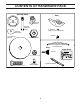
OPERATION These symbols may appear on your tractor or in literature supplied with the product. Learn and understand their meaning.
OPERATION KNOW YOUR TRACTOR READ THIS OWNER'S MANUAL AND SAFETY RULES BEFORE OPERATING YOUR TRACTOR Compare the illustrations with your tractor to familiarize yourself with the locations of various controls and adjustments. Save this manual for future reference. IGNITION SWITCH ATTACHMENT CLUTCH LEVER LIGHT SWITCH POSITION AMMETER THROTTLE/ CHOKE CONTROL LIFT LEVER PLUNGER ATTACHMENT LIFT LEVER CLUTCH/ BRAKE PEDAL PARKING BRAKE GEAR SHIFT LEVER FIG.
OPERATION The operation of any tractor can result in foreign objects thrown into the eyes, which can result in severe eye damage. Always wear safety glasses or eye shields while operating your tractor or performing any adjustments or repairs. We recommend a wide vision safety mask over spectacles or standard safety glasses. HOW TO USE YOUR TRACTOR NOTE: Under certain conditions when tractor is standing idle with the engine running, hot engine exhaust gases may cause “browning” of grass.
OPERATION TO ADJUST GAUGE WHEELS (See Fig. 7) "ENGAGED" POSITION Gauge wheels are properly adjusted when they are slightly off the ground when mower is at the desired cutting height in operating position. Gauge wheels then keep the deck in proper position to help prevent scalping in most terrain conditions. NOTE:Adjust gauge wheels with tractor on a flat level surface. • Adjust mower to desired cutting height (See “TO ADJUST MOWER CUTTING HEIGHT” in the Operation section of this manual).
OPERATION TO START ENGINE (See Fig. 6) BEFORE STARTING THE ENGINE When starting the engine for the first time or if the engine has run out of fuel, it will take extra cranking time to move fuel from the tank to the engine. • Sit on seat in operating position, depress clutch/brake pedal and set parking brake. • Place gear shift lever in neutral (N) position. • Move attachment clutch to “DISENGAGED” position. • Move throttle control to choke ( ) position.
OPERATION MOWING TIPS MULCHING MOWING TIPS • IMPORTANT: FOR BEST PERFORMANCE, KEEP MOWER HOUSING FREE OF BUILT-UP GRASS AND TRASH. CLEAN AFTER EACH USE. • • • • • • • Mower should be properly leveled for best mowing performance. See "TO LEVEL MOWER HOUSING" in the Service and Adjustments section of this manual. The left hand side of mower should be used for trimming. Drive so that clippings are discharged onto the area that has been cut. Have the cut area to the right of the machine.
CUSTOMER RESPONSIBILITIES MAINTENANCE SCHEDULE FILL IN DATES AS YOU COMPLETE REGULAR SERVICE E E S S RS AG US RS U R OUR OU SON OR H U O H C A A ST HO 25 H 50 H 100 SE RE EE Y 8 R RY ERY ERY ERY FO OR E E F BE SERVICE EV EV EV EV EV BE DATES Check Brake Operation Check Tire Pressure T R A C T 0 R Check Operator Presence and Interlock Systems Check for Loose Fasteners 5 Sharpen/Replace Mower Blades 3 Lubrication Chart Check Battery Level 4 Clean Battery and Terminals Check Transaxle Cooling Check
CUSTOMER RESPONSIBILITIES TRACTOR TRAILING EDGE UP Always observe safety rules when performing any maintenance. MANDREL ASSEMBLY BLADE CENTER HOLE BRAKE OPERATION FLAT WASHER If tractor requires more than six (6) feet stopping distance at high speed in highest gear, then brake must be adjusted. (See “TO ADJUST BRAKE” in the Service and Adjustments section of this manual).
CUSTOMER RESPONSIBILITIES TO CLEAN BATTERY AND TERMINALS Corrosion and dirt on the battery and terminals can cause the battery to “leak” power. • Disconnect BLACK battery cable first then RED battery cable and remove battery from tractor. • Rinse the battery with plain water and dry. • Clean terminals and battery cable ends with wire brush until bright. • Coat terminals with grease or petroleum jelly. • Reinstall battery (See “REPLACING BATTERY” in the Service and Adjustment section of this manual).
CUSTOMER RESPONSIBILITIES AIR FILTER (See Fig. 16) MUFFLER Your engine will not run properly using a dirty air filter. Clean the foam pre-cleaner after every 25 hours of operation or every season. Service paper cartridge every 100 hours of operation or every season, whichever occurs first. Service air cleaner more often under dusty conditions. • Remove knob(s) and cover. TO SERVICE PRE-CLEANER • Slide foam pre-cleaner off cartridge. • Wash it in liquid detergent and water.
SERVICE AND ADJUSTMENTS WARNING: TO AVOID SERIOUS INJURY, BEFORE PERFORMING ANY SERVICE OR ADJUSTMENTS: • Depress clutch/brake pedal fully and set parking brake. • Place gearshift lever in neutral (N) position. • Place attachment clutch in “DISENGAGED” position. • Turn ignition key to “STOP” and remove key. • Make sure the blades and all moving parts have completely stopped. • Disconnect spark plug wire from spark plug and place wire where it cannot come in contact with plug.
SERVICE AND ADJUSTMENTS • TO LEVEL MOWER HOUSING Adjust the mower while tractor is parked on level ground or driveway. Make sure tires are properly inflated (See “PRODUCT SPECIFICATIONS” section of this manual). If tires are over or underinflated, you will not properly adjust your mower. SIDE-TO-SIDE ADJUSTMENT (See Figs. 19 and 20) • Raise mower to its highest position. • At the midpoint of both sides of mower, measure height from bottom edge of mower to ground.
SERVICE AND ADJUSTMENTS BELT INSTALLATION • Carefully work new belt down between transaxle belt keepers and onto the input pulley. • Slide belt into the center span keeper. • Pull belt toward front of tractor and roll around the top groove of engine pulley. • Install belt through stationary idler and clutching idler. • Make sure belt is in all pulley grooves and inside all belt guides and keepers. • Install mower (See “TO INSTALL MOWER” in this section of manual). IDLER PULLEYS MANDREL PULLEYS FIG.
SERVICE AND ADJUSTMENTS TO ADJUST STEERING WHEEL ALIGNMENT BATTERY TO START OTHER VEHICLES. If steering wheel crossbars are not horizontal (left to right) when wheels are positioned straight forward, remove steering wheel and reassemble per instructions in the Assembly section of this manual. TO ATTACH JUMPER CABLES • Connect one end of the RED cable to the POSITIVE (+) terminal of each battery(A-B), taking care not to short against tractor chassis.
SERVICE AND ADJUSTMENTS SEAT PAN HEADLIGHT WIRE CONNECTOR HOOD FIG. 29 TERMINAL COVER KEPS NUT FIG. 31 ENGINE HEX BOLT TO ADJUST THROTTLE CONTROL CABLE (See Fig. 32) POSITIVE (RED) CABLE The throttle control has been preset at the factory and adjustment should not be necessary. Check adjustment as described below before loosening cable. If adjustment is necessary, proceed as follows: • With engine not running, move throttle control lever from slow to choke position.
STORAGE Immediately prepare your tractor for storage at the end of the season or if the tractor will not be used for 30 days or more. ENGINE FUEL SYSTEM CAUTION: Never store the tractor with gasoline in the tank inside a building where fumes may reach an open flame or spark. Allow the engine to cool before storing in any enclosure. IMPORTANT: IT IS IMPORTANT TO PREVENT GUM DEPOSITS FROM FORMING IN ESSENTIAL FUEL SYSTEM PARTS SUCH AS CARBURETOR, FUEL FILTER, FUEL HOSE, OR TANK DURING STORAGE.
TROUBLESHOOTING POINTS PROBLEM CAUSE Will not start 1. 2. 3. 4. 5. 6. 7. Out of fuel. Engine not “CHOKED” properly. Engine flooded. Bad spark plug. Dirty air filter. Dirty fuel filter. Water in fuel. 1. 2. 3. 4. 5. 6. 7. 8. 9. Loose or damaged wiring. Carburetor out of adjustment. 8. 9. 10. Hard to start CORRECTION Engine valves out of adjustment. 10. Fill fuel tank. See “TO START ENGINE” in Operation section. Wait several minutes before attempting to start. Replace spark plug.
TROUBLESHOOTING POINTS PROBLEM CAUSE CORRECTION Engine continues to run when operator leaves seat with attachment clutch engaged 1. Faulty operator-safety presence control system. 1. Check wiring, switches and connections. If not corrected, contact an authorized service center/ department. Poor cut - uneven 1. 2. 3. 4. 5. Worn, bent or loose blade. Mower deck not level. Buildup of grass, leaves, and trash under mower. Bent blade mandrel.
TRACTOR - - MODEL NUMBER PR1842STB PRODUCT NUMBER 954 56 82-05 SCHEMATIC RED BLACK BATTERY RED A RED FUSE AMMETER (OPTIONAL) M STARTER BLACK WHITE SOLENOID RED B S G BLACK L M CLUTCH / BRAKE (PEDAL UP) A1 A2 WHITE SEAT SWITCH (NOT OCCUPIED) IGNITION SWITCH WHITE BLACK BLACK BLACK BLACK HOUR METER ATT'MENT CLUTCH (CLUTCH OFF) GROUNDING CONNECTOR (OPTIONAL) BLUE SPARK PLUG GAP (2 PLUGS ON TWIN CYL.
REPAIR PARTS TRACTOR - - MODEL NUMBER PR1842STB PRODUCT NUMBER 954 56 82-05 ELECTRICAL 22 21 42 24 41 43 27 27 40 26 27 27 25 16 16 33 30 52 D.C .
REPAIR PARTS TRACTOR - - MODEL NUMBER PR1842STB PRODUCT NUMBER 954 56 82-05 ELECTRICAL KEY NO. PART NO.
REPAIR PARTS TRACTOR - - MODEL NUMBER PR1842STB PRODUCT NUMBER 954 56 82-05 CHASSIS AND ENCLOSURES 212 17 159 30 24 29 18 12 28 24 25 26 26 31 25 53 58 51 52 3 55 5 57 5 208 9 208 54 20 11 208 219 23 207 26 64 219 3 35 3 3 33 1 13 10 142 115 145 37 37 2 3 3 114 211 3 142 3 208 35 14 206 3 14 34 26 38 30
REPAIR PARTS TRACTOR - - MODEL NUMBER PR1842STB PRODUCT NUMBER 954 56 82-05 CHASSIS AND ENCLOSURES KEY NO. PART NO.
REPAIR PARTS TRACTOR - - MODEL NUMBER PR1842STB PRODUCT NUMBER 954 56 82-05 DRIVE 57 51 89 69 63 197 212 81 59 70 116 66 84 159 158 198 161 61 65 162 56 21 85 169 10 13 14 164 14 80 82 3 85 202 50 18 113 4 8 55 168 163 112 64 41 83 165 51 166 156 150 38 48 5 11 18 79 16 52 49 32 30 32 170 30 47 6 52 62 6 77 151 51 27 39 6 35 36 120 37 34 25 19 28 24 36 26 2 145 77 96 53 74 78 76 1 26 35 75 32 29 22 26 27
REPAIR PARTS TRACTOR - - MODEL NUMBER PR1842STB PRODUCT NUMBER 954 56 82-05 DRIVE KEY NO. PART NO.
REPAIR PARTS TRACTOR - - MODEL NUMBER PR1842STB PRODUCT NUMBER 954 56 82-05 STEERING ASSEMBLY 38 12 39 1 41 42 37 37 36 44 51 54 88 91 43 71 67 67 68 46 29 67 8 13 6 65 17 46 2 8 6 87 5 87 3 32 5 11 68 4 29 43 82 40 43 15 33 29 15 34 15 10 34 35 6 8
REPAIR PARTS TRACTOR - - MODEL NUMBER PR1842STB PRODUCT NUMBER 954 56 82-05 STEERING ASSEMBLY KEY NO. PART NO. DESCRIPTION 1 159944X428 Wheel Steering 2 172393 Axle Asm Cast Iron LT 3 169840 Spindle Asm LH 4 169839 Spindle Asm RH 5 6266H Bearing Race Thrust Harden 6 121748X Washer 25/32 X 1-5/8 X 16 Ga 8 12000029 Ring Klip #t5304-75 10 175121 Link Drag 11 10040600 Washer Lock Hvy Hlcl Spr 3/8 12 73940800 Nut Hex Jam Toplock 1/2-20 UNF 13 136518 Spacer Brg.
REPAIR PARTS TRACTOR - - MODEL NUMBER PR1842STB PRODUCT NUMBER 954 56 82-05 SEAT ASSEMBLY 1 8 8 9 14 9 7 7 10 5 6 22 21 2 24 5 16 25 15 11 4 13 17 3 12 KEY NO. PART NO. DESCRIPTION 1 2 3 4 5 6 7 8 9 10 11 171683 140551 71110616 19131610 145006 73800600 124181X 17000616 19131614 174894 166369 Seat Bracket Pivot Seat 8 720 Bolt Fin Hex 3/8-16 Unc X 1 Washer 13/32 X 1 X 10 Ga Clip Push-In Nut Hex w/Ins. 3/8-16 Unc Spring Seat Cprsn 2 250 Blk Zi Screw 3/8-16 X 1.5 Washer 13/32 X 1 X 14 Ga.
REPAIR PARTS TRACTOR - - MODEL NUMBER PR1842STB PRODUCT NUMBER 954 56 82-05 DECALS 2 16 11 4 4 3 10 2 20 9 1 8 6 18 5 14 KEY NO. 1 2 3 4 5 6 8 9 10 PART NO. 156369 176305 176308 182005 181564 179128 170563 172740 157140 19 DESCRIPTION Decal Oper Decal Fender Side Decal Hood LH Decal Side Panel Logo Decal HP Engine Decal Deck "B" 42" Decal Warning Mult-Language Decal Fender Logo Decal Fender Danger E/F KEY NO. 11 14 16 18 19 20 ------ PART NO.
REPAIR PARTS TRACTOR - - MODEL NUMBER PR1842STB PRODUCT NUMBER 954 56 82-05 ENGINE 3 2 72 62 1 81 38 78 32 16 44 14 78 46 33 37 31 112 41 40 45 33 23 29 OPTIONAL EQUIPMENT Spark Arrester 38 13 4
REPAIR PARTS TRACTOR - - MODEL NUMBER PR1842STB PRODUCT NUMBER 954 56 82-05 ENGINE KEY NO. PART NO.
REPAIR PARTS TRACTOR - - MODEL NUMBER PR1842STB PRODUCT NUMBER 954 56 82-05 MOWER DECK 67 157 158 68 156 153 151 40 37 36 40 155 152 143 153 154 144 45 150 40 37 159 46 106 145 103 102 105 105 44 59 56 53 52 55 51 48 54 142 49 147 50 148 104 103 146 33 32 31 104 106 101 102 30 132 34 91 21 182 21 94 183 95 132 1 147 116 2 21 142 113 111 114 21 23 24 115 117 25 26 2 119 16 118 28 15 14 20 27 29 18 3 4 114 18 149 13 5 112 115 6 11 19 21 10 9 118 119
REPAIR PARTS TRACTOR - - MODEL NUMBER PR1842STB PRODUCT NUMBER 954 56 82-05 MOWER DECK KEY NO. PART NO.
REPAIR PARTS TRACTOR - - MODEL NUMBER PR1842STB PRODUCT NUMBER 954 56 82-05 MOWER LIFT 7 8 41 5 37 38 40 1 36 3 13 4 6 2 11 6 5 4 12 13 19 13 20 15 31 32 13 19 20 17 18 20 16 20 15 31 32 42
REPAIR PARTS TRACTOR - - MODEL NUMBER PR1842STB PRODUCT NUMBER 954 56 82-05 MOWER LIFT KEY NO. 1 2 3 4 5 6 7 8 11 12 13 15 16 17 18 19 20 31 32 36 37 38 40 41 PART NO.
NOTES 44
LIMITED WARRANTY The Manufacturer warrants to the original consumer purchaser that this product as manufactured is free from defects in materials and workmanship. For a period of two (2) years from date of purchase by the original consumer purchaser, we will repair or replace, at our option, without charge for parts or labor incurred in replacing parts, any part which we find to be defective due to materials or workmanship. This Warranty is subject to the following limitations and exclusions. 1.
SERVICE ® TECUMSEH Issued January 1980 Revised January 1991 POLICY WARRANTY ® TECUMSEH LIMITED WARRANTIES FOR NEW PEERLESS GEAR POWER TRAIN COMPONENTS A.
SUGGESTED GUIDE FOR SIGHTING SLOPES FOR SAFE OPERATION FOL D AL ONG THIS DOT IS A TED 15 D LINE EGR EE S LOP E 47 ONLY RIDE UP AND DOWN HILL, NOT ACROSS HILL 15 DEGREES MAX. WARNING: To avoid serious injury, operate your tractor up and down the face of slopes, never across the face. Do not mow slopes greater than 15 degrees. Make turns gradually to prevent tipping or loss of control. Exercise extreme caution when changing direction on slopes. 1. Fold this page along dotted line indicated above. 2.
PARTS AND SERVICE Your POULAN PRO product has been expertly engineered and carefully manufactured to rigid quality standards. As with all mechanical products, some adjustments or part replacement may be necessary during the life of your unit. FOR SERVICE OR REPLACEMENT PARTS: 1. Consult your dealer/place of purchase. 2. Consult the yellow pages of your phone directory for the name of the nearest service dealer (under saws for Chain Saws or under lawn mowers for Trimmers, Brushcutters, and Blowers). 3.