MODEL NO. PC1538C 15 HP 38 Inch Lawn Tractor For Parts and Service, contact our authorized distributor: call 1-800-849-1297 For Technical Assistance: call 1-800-829-5886 186888 2.5.03 RD PRINTED IN U.S.A.
SAFETY RULES SAFE OPERATION PRACTICES FOR RIDE-ON MOWERS IMPORTANT: THIS CUTTING MACHINE IS CAPABLE OF AMPUTATING HANDS AND FEET AND THROWING OBJECTS. FAILURE TO OBSERVE THE FOLLOWING SAFETY INSTRUCTIONS COULD RESULT IN SERIOUS INJURY OR DEATH. I. GENERAL OPERATION • • • • • • • • • • • • • • • • • DO NOT: • Do not turn on slopes unless necessary, and then, turn slowly and gradually downhill, if possible. • Do not mow near drop-offs, ditches, or embankments.
SAFETY RULES Safe Operation Practices for Ride-On Mowers • • • • • • • • • • • • • • Be sure the area is clear of other people before mowing. Stop machine if anyone enters the area. Never carry passengers or children even with the blades off. Do not mow in reverse unless absolutely necessary. Always look down and behind before and while backing. Never carry children. They may fall off and be seriously injured or interfere with safe machine operation.
CONGRATULATIONS on your purchase of a new tractor. It has been designed, engineered and manufactured to give you the best possible dependability and performance. Should you experience any problem you cannot easily remedy, please contact your nearest authorized service center/ department. We have competent, well-trained technicians and the proper tools to ser vice or repair this tractor. Please read and retain this manual. The instructions will enable you to assemble and maintain your tractor properly.
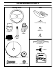
UNASSEMBLED PARTS Steering Wheel Seat (1) Washer 17/32 x 1-3/16 x 12 Gauge (1) Lock Washer 1/2 Steering Wheel Insert Steering Wheel Adapter Steering Boot Steering Extension Shaft (1) Bolt (1) Oil Drain Tube For Future Use Keys (2) Keys Slope Sheet (1) Large Flat Washer (1) Hex Bolt 1/4-28 x 1-1/4 (1) Locknut 1/2-20 (1) Locknut 1/4-28 5
ASSEMBLY Your new tractor has been assembled at the factory with exception of those parts left unassembled for shipping purposes. To ensure safe and proper operation of your tractor all parts and hardware you assemble must be tightened securely. Use the correct tools as necessary to insure proper tightness. TOOLS REQUIRED FOR ASSEMBLY INSERT A socket wrench set will make assembly easier. Standard wrench sizes are listed.
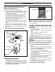
ASSEMBLY HOW TO SET UP YOUR TRACTOR INSTALL SEAT (See Fig. 2) SEAT PAN Adjust seat before tightening adjustment bolt. • Remove adjustment bolt, lock washer and flat washer securing seat to cardboard packing and set aside for assembly of seat to tractor. • Pivot seat upward and remove from the cardboard packing. Remove the cardboard packing and discard. • Place seat on seat pan so head of shoulder bolt is positioned over large slotted hole in pan.
ASSEMBLY ✓CHECKLIST CHECK TIRE PRESSURE The tires on your tractor were overinflated at the factory for shipping purposes. Correct tire pressure is important for best cutting performance. • Reduce tire pressure to PSI shown in “PRODUCT SPECIFICATIONS” section of this manual. BEFORE YOU OPERATE AND ENJOY YOUR NEW TRACTOR, WE WISH TO ASSURE THAT YOU RECEIVE THE BEST PERFORMANCE AND SATISFACTION FROM THIS QUALITY PRODUCT. PLEASE REVIEW THE FOLLOWING CHECKLIST: ✓ All assembly instructions have been completed.
OPERATION These symbols may appear on your tractor or in literature supplied with the product. Learn and understand their meaning.
OPERATION KNOW YOUR TRACTOR READ THIS OWNER'S MANUAL AND SAFETY RULES BEFORE OPERATING YOUR TRACTOR Compare the illustrations with your tractor to familiarize yourself with the locations of various controls and adjustments. Save this manual for future reference. IGNITION SWITCH ATTACHMENT CLUTCH LEVER LIGHT SWITCH POSITION LIFT LEVER PLUNGER THROTTLE/CHOKE CONTROL ATTACHMENT LIFT LEVER CLUTCH/BRAKE PEDAL MOWER DECK HEIGHT ADJUSTMENT POSITIONS PARKING BRAKE GEARSHIFT LEVER FIG.
OPERATION The operation of any tractor can result in foreign objects thrown into the eyes, which can result in severe eye damage. Always wear safety glasses or eye shields while operating your tractor or performing any adjustments or repairs. We recommend a wide vision safety mask over spectacles or standard safety glasses. IMPORTANT: LEAVING THE IGNITION SWITCH IN ANY POSITION OTHER THAN "OFF" WILL CAUSE THE BATTERY TO BE DISCHARGED, (DEAD). HOW TO USE YOUR TRACTOR TO SET PARKING BRAKE (See Fig.
OPERATION TO OPERATE MOWER (See Fig. 6) TO TRANSPORT Your tractor is equipped with an operator presence sensing switch. Any attempt by the operator to leave the seat with the engine running and the attachment clutch engaged will shut off the engine. • Select desired height of cut. • Start mower blades by engaging attachment clutch control. • TO STOP MOWER BLADES - disengage attachment clutch control. • Raise attachment lift to highest position with attachment lift control.
OPERATION MOWING TIPS CAUTION: Alcohol blended fuels (called gasohol or using ethanol or methanol) can attract moisture which leads to separation and formation of acids during storage. Acidic gas can damage the fuel system of an engine while in storage. To avoid engine problems, the fuel system should be emptied before storage of 30 days or longer. Drain the gas tank, start the engine and let it run until the fuel lines and carburetor are empty. Use fresh fuel next season.
MAINTENANCE MAINTENANCE SCHEDULE FILL IN DATES AS YOU COMPLETE REGULAR SERVICE E E S S RS AG US RS UR OUR OU SON OR U O H O H H A 0 ST E 8H SE RE 25 10 50 Y Y Y Y Y RE O R R R R R O F E E E E E F BE SERVICE EV EV EV EV EV BE H AC DATES Check Brake Operation Check Tire Pressure T R A C T 0 R Check Operator Presence and Interlock Systems Check for Loose Fasteners 5 Sharpen/Replace Mower Blades 3 Lubrication Chart Check Battery Level 4 Clean Battery and Terminals Check Transaxle Cooling Check V-Belt
MAINTENANCE TRACTOR MANDREL ASSEMBLY TRAILING EDGE UP Always observe safety rules when performing any maintenance. CENTER HOLE BRAKE OPERATION If tractor requires more than six (6) feet stopping distance at high speed in highest gear, then brake must be adjusted. (See “TO ADJUST BRAKE” in the Service and Adjustments section of this manual). LOCK WASHER STAR TIRES • Maintain proper air pressure in all tires (See “PRODUCT SPECIFICATIONS” section of this manual).
MAINTENANCE NOTE: Although multi-viscosity oils (5W30, 10W30 etc.) improve starting in cold weather, these multi-viscosity oils will result in increased oil consumption when used above 32°F. Check your engine oil level more frequently to avoid possible engine damage from running low on oil. Change the oil after every 25 hours of operation or at least once a year if the tractor is not used for 25 hours in one year.
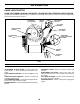
MAINTENANCE CLEAN AIR SCREEN AIR FILTER (See Fig. 13) Air screen must be kept free of dirt and chaff to prevent engine damage from overheating. Clean with a wire brush or compressed air to remove dirt and stubborn dried gum fibers. Your engine will not run properly using a dirty air filter. Replace pre-cleaner after every 25 hours of operation or every season. Service paper cartridge every 100 hours of operation or every season, whichever occurs first.
MAINTENANCE MUFFLER Inspect and replace corroded muffler and spark arrester (if equipped) as it could create a fire hazard and/or damage. CLAMP CLAMP SPARK PLUGS Replace spark plugs at the beginning of each mowing season or after every 100 hours of operation, whichever occurs first. Spark plug type and gap setting are shown in “PRODUCT SPECIFICATIONS” section of this manual. FUEL FILTER FIG. 14 IN-LINE FUEL FILTER (See Fig. 14) The fuel filter should be replaced once each season.
SERVICE AND ADJUSTMENTS WARNING: TO AVOID SERIOUS INJURY, BEFORE PERFORMING ANY SERVICE OR ADJUSTMENTS: • Depress clutch/brake pedal fully and set parking brake. • Place gearshift lever in neutral (N) position. • Place attachment clutch in “DISENGAGED” position. • Turn ignition key to “STOP” and remove key. • Make sure the blades and all moving parts have completely stopped. • Disconnect spark plug wire from spark plug and place wire where it cannot come in contact with plug.
SERVICE AND ADJUSTMENTS TO LEVEL MOWER HOUSING Adjust the mower while tractor is parked on level ground or driveway. Make sure tires are properly inflated (See “PRODUCT SPECIFICATIONS” section of this manual). If tires are over or underinflated, you will not properly adjust your mower. • • SIDE-TO-SIDE ADJUSTMENT (See Figs. 16 and 17) • Raise mower to its highest position. • At the midpoint of both sides of mower, measure height from bottom edge of mower to ground.
SERVICE AND ADJUSTMENTS TO REPLACE MOTION DRIVE BELT (See Fig. 22) R.H. SUSPENSION ARM Park the tractor on level surface. Engage parking brake. For assistance, there is a belt installation guide decal on bottom side of left footrest. BELT REMOVAL • Remove mower (See “TO REMOVE MOWER” in this section of manual). NOTE: Observe entire motion drive belt and position of all belt guides and keepers. • Remove belt from stationary idler and clutching idler. • Remove belt downward from around engine pulley.
SERVICE AND ADJUSTMENTS • Position the gear shift lever in the neutral (N) position. • Tighten adjustment bolt securely. NOTE: If additional clearance is needed to get to adjustment bolt, move mower deck height to the lowest position. WASHERS RETAINING RING AXLE COVER SQUARE KEY (REAR WHEEL ONLY) GEARSHIFT LEVER FIG. 24 TO START ENGINE WITH A WEAK BATTERY (See Fig. 25) WARNING: Lead-acid batteries generate explosive gases. Keep sparks, flame and smoking materials away from batteries.
SERVICE AND ADJUSTMENTS • • • • • Lift seat pan to raised position. Disconnect BLACK battery cable first then RED battery cable and carefully remove battery from tractor. Install new battery with terminals in same position as old battery. First connect RED battery cable to positive (+) terminal with hex bolt and keps nut as shown. Tighten securely. Slide terminal cover over terminal. Connect BLACK grounding cable to negative (-) terminal with remaining hex bolt and keps nut. Tighten securely.
STORAGE ENGINE Immediately prepare your tractor for storage at the end of the season or if the tractor will not be used for 30 days or more. FUEL SYSTEM IMPORTANT: IT IS IMPORTANT TO PREVENT GUM DEPOSITS FROM FORMING IN ESSENTIAL FUEL SYSTEM PARTS SUCH AS CARBURETOR, FUEL FILTER, FUEL HOSE, OR TANK DURING STORAGE. ALSO, EXPERIENCE INDICATES THAT ALCOHOL BLENDED FUELS (CALLED GASOHOL OR USING ETHANOL OR METHANOL) CAN ATTRACT MOISTURE WHICH LEADS TO SEPARATION AND FORMATION OF ACIDS DURING STORAGE.
TROUBLESHOOTING POINTS PROBLEM Will not start CAUSE 1. 2. 3. 4. 5. 6. 7. Out of fuel. Engine not “CHOKED” properly. Engine flooded. Bad spark plug. Dirty air filter. Dirty fuel filter. Water in fuel. 1. 2. 3. 4. 5. 6. 7. 8. 9. Loose or damaged wiring. Carburetor out of adjustment. 8. 9. 10. Hard to start CORRECTION Engine valves out of adjustment. 10. Fill fuel tank. See “TO START ENGINE” in Operation section. Wait several minutes before attempting to start. Replace spark plug.
TROUBLESHOOTING POINTS PROBLEM CAUSE CORRECTION Engine continues to run when operator leaves seat with attachment clutch engaged 1. Faulty operator-safety presence control system. 1. Check wiring, switches and connections. If not corrected, contact an authorized service center/ department. Poor cut - uneven 1. 2. 3. 4. 5. Worn, bent or loose blade. Mower deck not level. Buildup of grass, leaves, and trash under mower. Bent blade mandrel.
TRACTOR - - MODEL NUMBER PC1538C, PRODUCT NUMBER 954 57 09-32 SCHEMATIC RED BLACK BATTERY RED A RED FUSE AMMETER (OPTIONAL) M STARTER BLACK WHITE SOLENOID RED B S G BLACK L M CLUTCH / BRAKE (PEDAL UP) A1 A2 WHITE SEAT SWITCH (NOT OCCUPIED) IGNITION SWITCH WHITE BLACK BLACK BLACK BLACK HOUR METER ATT'MENT CLUTCH (CLUTCH OFF) GROUNDING CONNECTOR (OPTIONAL) BLUE SPARK PLUG GAP (2 PLUGS ON TWIN CYL.
REPAIR PARTS TRACTOR - - MODEL NUMBER PC1538C, PRODUCT NUMBER 954 57 09-32 ELECTRICAL 22 21 42 24 41 43 27 27 40 26 27 27 25 16 16 33 30 48 52 29 8 28 27 2 90 1 28
REPAIR PARTS TRACTOR - - MODEL NUMBER PC1538C, PRODUCT NUMBER 954 57 09-32 ELECTRICAL KEY NO. PART NO.
REPAIR PARTS TRACTOR - - MODEL NUMBER PC1538C, PRODUCT NUMBER 954 57 09-32 CHASSIS 212 17 30 24 29 18 12 28 24 26 25 26 31 209 25 53 51 5 52 55 57 5 209 9 209 208 11 208 54 207 26 64 3 35 3 3 3 33 1 13 10 142 145 37 37 3 3 2 206 3 142 3 3 208 35 14 14 38 30 34 26 chassis-pl.
REPAIR PARTS TRACTOR - - MODEL NUMBER PC1538C, PRODUCT NUMBER 954 57 09-32 CHASSIS KEY NO. PART NO.
REPAIR PARTS TRACTOR - - MODEL NUMBER PC1538C, PRODUCT NUMBER 954 57 09-32 DRIVE 57 51 89 69 63 197 212 81 59 70 116 66 84 159 158 198 161 61 65 162 56 21 85 10 13 14 164 169 14 80 82 3 85 202 50 18 113 4 8 55 168 163 112 64 41 83 165 51 166 156 150 38 48 5 11 18 79 16 52 49 32 30 32 170 30 47 6 52 62 6 77 151 51 27 39 6 35 36 120 37 34 25 19 28 24 36 26 2 145 77 96 53 74 78 76 1 26 35 75 32 29 22 26 27
REPAIR PARTS TRACTOR - - MODEL NUMBER PC1538C, PRODUCT NUMBER 954 57 09-32 DRIVE KEY NO. PART NO.
REPAIR PARTS TRACTOR - - MODEL NUMBER PC1538C, PRODUCT NUMBER 954 57 09-32 STEERING 38 12 39 1 41 42 37 37 36 44 51 54 88 91 43 71 68 67 67 29 46 8 47 6 9 17 67 13 65 46 85 2 8 7 85 6 9 9 5 47 7 3 32 9 5 68 11 82 29 26 4 43 15 40 15 43 29 28 15 10 30 34 6 8
REPAIR PARTS TRACTOR - - MODEL NUMBER PC1538C, PRODUCT NUMBER 954 57 09-32 STEERING KEY NO. PART NO.
REPAIR PARTS TRACTOR - - MODEL NUMBER PC1538C, PRODUCT NUMBER 954 57 09-32 ENGINE 3 2 72 1 81 13 78 38 32 14 16 44 78 46 33 37 31 40 33 29 45 23 OPTIONAL EQUIPMENT Spark Arrester 36 4
REPAIR PARTS TRACTOR - - MODEL NUMBER PC1538C, PRODUCT NUMBER 954 57 09-32 ENGINE KEY NO. PART NO.
REPAIR PARTS TRACTOR - - MODEL NUMBER PC1538C, PRODUCT NUMBER 954 57 09-32 SEAT 1 8 8 9 14 9 7 7 10 5 6 22 21 2 24 5 26 16 25 15 23 4 13 17 KEY NO. 1 2 3 4 5 6 7 8 9 10 12 13 PART NO. 127426X 140551 71110616 19131610 145006 73800600 124181X 17000616 19131614 182493 121246X 121248X 3 12 KEY NO. 14 15 16 17 21 22 23 24 25 26 DESCRIPTION Seat Bracket Seat Pivot Bolt Hex 3/8 - 16 X 1 Washer 13/32 X 1 X10Ga.
REPAIR PARTS TRACTOR - - MODEL NUMBER PC1538C, PRODUCT NUMBER 954 57 09-32 DECALS 8 12 7 14 1 6 8 15 9 16 4 3 17 KEY NO. PART NO. DESCRIPTION KEY NO. 1 3 4 6 7 8 9 12 14 15 16 185413 184768 170563 157140 158168 172200 158166 181552 181553 145005 156369 NPR Decal Replace Decal, Engine HP Decal Warning Decal, Fender Danger English Decal Ins Str Wh Decal, Fender 5 Sp. Decal Fender Decal, Hood RH Decal, Hood LH Decal, Caution, Battery Decal, Oper Inst. 17 136832 Decal, V-Belt Sch.
REPAIR PARTS TRACTOR - - MODEL NUMBER PC1538C, PRODUCT NUMBER 954 57 09-32 MOWER LIFT 7 8 5 1 3 13 2 4 6 6 11 5 4 12 13 19 20 13 15 31 32 13 19 20 17 18 20 16 20 15 31 32 40
REPAIR PARTS TRACTOR - - MODEL NUMBER PC1538C, PRODUCT NUMBER 954 57 09-32 MOWER LIFT KEY NO. PART NO.
REPAIR PARTS TRACTOR - - MODEL NUMBER PC1538C, PRODUCT NUMBER 954 57 09-32 MOWER DECK 40 146 89 42 157 68 148 107 67 38 108 158 36 156 153 151 89 155 56 152 36 153 154 69 33 32 55 31 40 54 150 2 123 45 110 113 21 122 53 30 1 21 88 109 87 89 24 25 28 26 97 96 21 2 86 2 21 2 23 15 16 29 14 3 5 27 13 4 6 11 19 21 10 9 8 149 42
REPAIR PARTS TRACTOR - - MODEL NUMBER PC1538C, PRODUCT NUMBER 954 57 09-32 MOWER DECK KEY NO. 1 2 3 4 5 6 8 9 10 11 11 11 13 14 15 16 19 21 23 24 25 26 27 28 29 30 31 32 33 36 40 45 53 PART NO. 170280 72140506 138017 169970 4939M 178024 850857 10030600 140296 DESCRIPTION Mower Housing Assembly Bolt Carriage 5/16-18 x 3/4 Bracket Asm Fr. Sway Bar Bracket Deck Sway Bar 38"/42" Retainer Spring Bar Sway Deck Bolt 3/8-24 x 1.
SERVICE NOTES 44
LIMITED WARRANTY The Manufacturer warrants to the original consumer purchaser that this product as manufactured is free from defects in materials and workmanship. For a period of two (2) years from date of purchase by the original consumer purchaser, we will repair or replace, at our option, without charge for parts or labor incurred in replacing parts, any part which we find to be defective due to materials or workmanship. This Warranty is subject to the following limitations and exclusions. 1.
SERVICE ® TECUMSEH Issued January 1980 Revised January 1991 POLICY WARRANTY ® TECUMSEH LIMITED WARRANTIES FOR NEW PEERLESS GEAR POWER TRAIN COMPONENTS A.
SUGGESTED GUIDE FOR SIGHTING SLOPES FOR SAFE OPERATION FOL D AL ONG THIS DOT IS A TED 15 D LINE EGR EE S LOP E 47 ONLY RIDE UP AND DOWN HILL, NOT ACROSS HILL 15 DEGREES MAX. WARNING: To avoid serious injury, operate your tractor up and down the face of slopes, never across the face. Do not mow slopes greater than 15 degrees. Make turns gradually to prevent tipping or loss of control. Exercise extreme caution when changing direction on slopes. 1. Fold this page along dotted line indicated above. 2.