IMPORTANT MANUAL Do Not Throw Away OWNER'S MANUAL MODEL NUMBER: PP10527ESA SNOW THROWER WARNING: Read the Owner's Manual and follow all Warnings and Safety Instructions. Failure to do so can result in serious injury. Always Wear Eye Protection During Operation 188047 Rev. 1 04.08.04 BY Printed in U.S.A.
SAFETY RULES Safe Operation Practices for Snow Throwers IMPORTANT: This machine is capable of amputating hands and feet and throwing objects. Failure to observe the following safety instructions could result in serious injury or death. • Do not operate the equipment without wearing adeLook for this symbol to point out imquate winter outer garments. Avoid loose, dangling portant safety precautions. It means clothing, such as scarves, which can get caught in CAUTION!!! BECOME ALERT!!! YOUR rotating parts.
• • • • • • • • Do not put hands or feet near or under rotating parts. Keep clear of the discharge opening and front auger area at all times. Exercise extreme caution when operating on or crossing gravel drives, walks or roads. Stay alert for hidden hazards or traffic. After striking a foreign object, stop the engine (motor), remove wire from the spark plug, thoroughly inspect snow thrower for any damage, and repair the damage before restarting and operating the snow thrower.
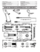
SAFETY RULES ........................................................ 2-3 PRODUCT SPECIFICATIONS ...................................... 3 CUSTOMER RESPONSIBILITIES................................ 3 WARRANTY................................................................ 32 ASSEMBLY / PRE-OPERATION ............................... 5-7 OPERATION ............................................................ 8-13 MAINTENANCE ..................................................... 14-15 MAINTENANCE SCHEDULE .......
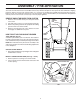
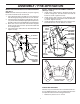
ASSEMBLY / PRE-OPERATION Read these instructions and this manual in its entirety before you attempt to assemble or operate your new snow thrower. Your new snow thrower has been assembled at the factory with the exception of those parts left unassembled for shipping purposes. All parts such as nuts, washers, bolts, etc., necessary to complete the assembly have been placed in the parts bag.
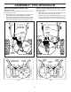
ASSEMBLY / PRE-OPERATION INSTALL TRACTION DRIVE CONTROL ROD (See Figs. 3 and 4) The traction drive control rod has the long loop on the end of the spring as shown. 1. Slide rubber sleeve up rod and hook end of spring into pivot bracket with loop opening down as shown. 2. With top end of rod positioned under left side of control panel, push rod down and insert top end of rod into hole in drive control bracket. Secure with retainer spring. INSTALL AUGER CONTROL ROD (See Figs.
ASSEMBLY / PRE-OPERATION INSTALL CHUTE DEFLECTOR REMOTE CONTROL (See Figs. 8 and 9) 1. Install remote cable bracket to discharge chute with 5/16-18 carriage bolt, 5/16 flat washer and 5/16-18 locknut as shown. Tighten securely. 2. Install remote cable eyelet to chute deflector with 1/4-20 shoulder bolt, 1/4 flat washer and 1/4-20 locknut as shown. Tighten securely. 3. Install spring hooks between hex nuts on chute rotater head and into hole in chute deflector as shown.
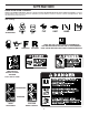
OPERATION KNOW YOUR SNOW THROWER READ THIS OWNER'S MANUAL AND ALL SAFETY RULES BEFORE OPERATING YOUR SNOW THROWER. Compare the illustrations with your snow thrower to familiarize yourself with the location of various controls and adjustments. Save this manual for future reference. These symbols may appear on your snow thrower or in literature supplied with the product. Learn and understand their meaning.
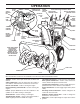
OPERATION SPARK PLUG ENGINE OIL CAP WITH DIPSTICK SAFETY IGNITION KEY AUGER CONTROL LEVER DISCHARGE CHUTE CONTROL LEVER DRIVE SPEED CONTROL LEVER GASOLINE FILLER CAP CHUTE DEFLECTOR CHOKE CONTROL DEFLECTOR REMOTE CONTROL LEVER TRACTION DRIVE CONTROL LEVER LH TURN TRIGGER THROTTLE / ENGINE CONTROL LIGHT OIL DRAIN PLUG RECOIL (AUXILIARY) STARTER HANDLE POWER CORD PLUG ELECTRIC START FUEL SHUT-OFF VALVE BUTTON DISCHARGE PRIMER CHUTE HANDLE KNOB MUFFLER NOTE: ITEMS ABOVE ARE SHOWN IN THEIR TYPICA
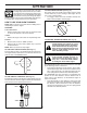
OPERATION TO USE CHOKE CONTROL (See Fig. 13) The choke control is located on the engine. Use the choke control whenever you are starting a cold engine. Do not use to start a warm engine. • To engage choke, turn knob clockwise. Slowly turn knob counterclockwise to disengage. The operation of any snow thrower can result in foreign objects thrown into the eyes, which can result in severe eye damage.
OPERATION DISCHARGE CHUTE CONTROL LEVER CAUTION: Do not move speed control lever when traction drive control lever is engaged. Damage to the snow thrower can result. • Slower speeds are for heavier snow and faster speeds are for light snow and transporting the snow thrower. It is recommended that you use a slower speed until you are familiar with the operation of the snow thrower.
OPERATION TO ADJUST SKID PLATES (See Fig. 18) NOTE: The wrench provided in your parts bag may be used to adjust the skid plates. Skid plates are located on each side of the auger housing and adjust the clearance between the scraper bar and the ground surface. Adjust skid plates evenly to proper height for current surface conditions.
OPERATION ELECTRIC STARTER 1. Connect the power cord to the engine. 2. Plug the other end of the power cord into a three-hole grounded 120 Volt A.C. receptacle. 3. While the engine is running, push starter button and spin the starter for several seconds. NOTE: The unusual sound made while starter is spinning will not harm the engine or starter. 4. Disconnect the power cord from the receptacle first, then from the engine. RECOIL STARTER 1.
MAINTENANCE GENERAL RECOMMENDATIONS LUBRICATION CHART The warranty on this snow thrower does not cover items that have been subjected to operator abuse or negligence. To receive full value from the warranty, operator must maintain snow thrower as instructed in this manual. Some adjustments will need to be made periodically to properly maintain your snow thrower. All adjustments in the Service and Adjustments section of this manual should be checked at least once each season.
MAINTENANCE V-BELTS Check V-belts for deterioration and wear after every 50 hours of operation and replace if necessary. The belts are not adjustable. Replace belts if they begin to slip from wear. (See “TO REMOVE BELT COVER” in the Service and Adjustments section of this manual). The V-belts on your snow thrower are of special construction and should be replaced by original equipment manufacturer (OEM) belts available from your nearest dealer.
SERVICE AND ADJUSTMENTS WARNING: To avoid serious injury, before performing any service or adjustments: 1. Be sure throttle is in STOP position. 2. Remove safety ignition key. 3. Make sure the augers and all moving parts have completely stopped. 4. Disconnect spark plug wire from spark plug and place wire where it cannot come in contact with plug. 1. Disengage all controls and move throttle control to STOP position. Wait for all moving parts to stop. 2.
SERVICE AND ADJUSTMENTS TO REPLACE BELTS (See Fig. 22) The auger and traction drive belts are not adjustable. If the belts are damaged or begin to slip from wear, they should be replaced. It is recommended that the belt(s) be replaced by a qualified service center. NOTE: It is recommended that both the auger and traction drive belt be replaced at the same time.
TO REMOVE WHEELS (See Fig. 23) • Remove the klik pin and remove wheel from axle. IMPORTANT: When installing wheel, be sure to use the axle hole closest to the end of the shaft – do not use the hole in the wheel hub (if equipped). Inner hole in axle and hole in wheel hub are not used for your model snow thrower. KLIK PIN (INSTALL IN OUTER HOLE OF AXLE ONLY) OUTER HOLE AXLE WHEEL HUB WHEEL FIG.
TROUBLESHOOTING See appropriate section in manual unless directed to a qualified service center. PROBLEM Does not start CAUSE CORRECTION 1. Fuel shut-off valve (if so equipped) in OFF position. 2. Safety ignition key is not inserted. 3. Out of fuel. 4. Throttle in STOP position. 5. Choke in OFF position. 6. Primer not depressed. 7. Engine is flooded. 8. Spark plug wire is disconnected. 9. Bad spark plug. 10. Stale fuel. 11. Water in fuel. 1. Turn fuel shut-off valve to OPEN position. 1.
LIMITED WARRANTY The Manufacturer warrants to the original consumer purchaser that this product as manufactured is free from defects in materials and workmanship. For a period of two (2) years from date of purchase by the original consumer purchaser, we will repair or replace, at our option, without charge for parts or labor incurred in replacing parts, any part which we find to be defective due to materials or workmanship. This Warranty is subject to the following limitations and exclusions. 1.