
Manual


AIR FILTER
CAUTION: Do not clean filter in gasoline
or other flammable solvent to avoid creating
a fire hazard or producing harmful evapora-
tive emissions.
Cleaning the air filter:
A dirty air filter decreases engine perform-
ance and increases fuel consumption and
harmful emissions. Always clean after every
5 hours of operation.
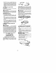
1. Loosen 3 screws on cylinder cover.
2. Remove cylinder cover.
3. Remove air filter.
4. Clean the fflr filter using hot soapywater.
Rinse with clean cool water. Air dry
completely before rfflnstalling.
5. Lightly oil air filter beforeinstalling to im-
prove the efficiency of air filter. Use
2~cycle engine oil or motor oil (SAE 30).
Squeeze excess oil from filter.
6. Reinstall air filter.
7. Reinstall cylinder cover and 3 screws.
Tighten securely.
.... Cylinder Cover
Air Filter J-fJ Screws
_°S "_ _€
vinder
INSPECT MUFFLER AND SPARK
ARRESTING SCREEN
,_IkWARNING: The muffler on this
product contains chemicals known to the
State of CaiJforffla to cause cancer.
As the unit is used, carbon deposits build up
on the muffler and spark arresting screen,
and must be removed to avoid creating a fire
hazard or affecting engine performance.
Replace the spark arresting screen if breaks
occur.
CLEANING THE SPARK ARREST-
ING SCREEN
Cleaning Js required every 25 hours of op_
eration or annually, whichever comes first.
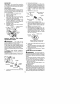
_i utlet
Guide
Muffler
_, _,_"_/o_ /_ Muffler
Backplate Bolts
Muffler -,.,_
Gasket _'_"_ _.
Bolt Cover "_
Locknut
1. Loosen and removethelocknut from the
bolt cover.
2. Remove the bolt cover.
3. Loosen and remove the 2 muffler bolts.
Remove the muffler, muffler gasket, out-
let guide and backplate. Notice the ori-
entafion of these parts for reassembling.
4. Locate the 2 ouflet cover screws on the
muffler. Loosen and remove both
screws.
5. Removethe ouflet cover.
_, Outlet Cover BACK VIEW OF
6.
7.
8.
9.
Remove spark arresting screen.
Clean the spark arresting screen with a
wire brush. Replace screen if any wires
are broken or screen is blocked after clea-
ning.
Reinstall spark arresting screen.
Rfflnstall outlet cover and 2 screws. En-
sure outiet cover and both screws are
rfflnstalled correctly (see illustrations) to
prevent damage to the saw. The ex-
haust outlet must face the chffln brake
(bar side) of the saw.
Outlet Cover
Exhaust _ _/
outlet
Exhaust Outlet must face chain
brake (bar side) of chain saw
10. inspect the muffier gasket and replace if
damaged.
11. Reinstall backplate, ouflet guide, muffler
gasket, and muffler using muffler bolts.
Tighten until secure.
12. Reinstall boltcover andlocknut. Tighten
securely.
CARBURETOR ADJUSTMENT
_k WARNING: The chain will be mov-
ing during most of this procedure. Wear your
protective equipment and observe all safety
precautions. The chain must not move at idle
speed.
The carburetor has been carefully set at the
factory. Adjustments may be necessary if
you notice any of the following conditions:
• Chain moves at idle. See tDLE SPEED-T
adjusting procedure.
• Saw will not idle. See IDLE SPEED~T ad-
justing procedure.
Idle Speed-T
Allow engine to idle. If the chain moves, idle
istoofast. Ifthe engine stalls, idle is too slow.
Adjust speed until engine runs without chain
movement (idle too fast) or stalling (idle too
slow). The idle speed screw is located in the
area above the primer bulb and is labffled T.
14