IMPORTANT MANUAL Do Not Throw Away OWNER'S MANUAL MODEL NUMBER: PP10530ES SNOW THROWER WARNING: Read the Owner's Manual and follow all Warnings and Safety Instructions. Failure to do so can result in serious injury. Always Wear Eye Protection During Operation 416833 09.12.07 TH Printed in the U.S.A.
IMPORTANT Safe Operation Practices for Walk-Behind Snow Throwers This snow thrower is capable of amputating hands and feet and throwing objects. Failure to observe the following safety instructions could result in serious injury. WARNING: Snow throwers have exposed rotating parts, which can cause severe injury from contact, or from material thrown from the discharge chute. Keep the area of operation clear of all persons, small children and pets at all times including startup.
6. When cleaning, repairing or inspecting the snow thrower, stop the engine and make certain the collector/impeller and all moving parts have stopped. Disconnect the spark plug wire and keep the wire away from the plug to prevent someone from accidentally starting the engine. 7. Do not run the engine indoors, except when starting the engine and for transporting the snow thrower in or out of the building. Open the outside doors; exhaust fumes are dangerous. 8.
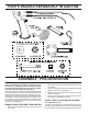
PARTS PACKED SEPARATELY IN CARTON ASSEMBLY / PRE-OPERATION 2. Cut down all four corners of carton and lay panels flat. 3. Remove the two (2) screws securing the auger housing to the pallet. 4. Remove all packing materials except plastic tie holding speed control rod to lower handle. 5. Remove the two (2) plastic ties securing the upper handle to the pallet. 6. Remove snow thrower from carton and check carton thoroughly for additional loose parts.
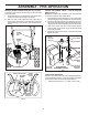
ASSEMBLY / PRE-OPERATION NOTE: The multi-wrench may be used for assembly of the chute rotator head to snow thrower and making adjustments to the skid plates. INSTALL TRACTION DRIVE CONTROL ROD (See Figs. 3 and 4) The traction drive control rod has the long loop on the end of the spring as shown. 1. Slide rubber sleeve up rod and hook end of spring into pivot bracket with loop opening down as shown. 2.
ASSEMBLY / PRE-OPERATION INSTALL AUGER CONTROL ROD (See Figs. 5 and 6) The auger control rod has the short loop on the end of the spring as shown. 1. Slide rubber sleeve up rod and hook end of spring into control arm with loop opening up as shown. 2. With top end of rod positioned under right side of control panel, push down on rod and insert end of rod into hole in auger control bracket. Secure with retainer spring. INSTALL DISCHARGE CHUTE / CHUTE ROTATOR HEAD (See Fig.
OPERATION KNOW YOUR SNOW THROWER READ THIS OWNER'S MANUAL AND ALL SAFETY RULES BEFORE OPERATING YOUR SNOW THROWER. Compare the illustrations with your snow thrower to familiarize yourself with the location of various controls and adjustments. Save this manual for future reference. These symbols may appear on your snow thrower or in literature supplied with the product. Learn and understand their meaning.
OPERATION SPARK PLUG SAFETY IGNITION KEY ENGINE OIL CAP WITH DIPSTICK AUGER CONTROL LEVER DRIVE SPEED CONTROL LEVER DISCHARGE CHUTE CONTROL LEVER TRACTION DRIVE CONTROL LEVER GASOLINE FILLER CAP CHUTE DEFLECTOR CHOKE CONTROL OIL DRAIN PLUG THROTTLE / ENGINE CONTROL DISCHARGE CHUTE RECOIL (AUXILIARY) STARTER HANDLE POWER CORD PLUG ELECTRIC START FUEL BUTTON SHUT-OFF VALVE PRIMER HANDLE KNOB CLEANOUT TOOL MUFFLER NOTE: ITEMS ABOVE ARE SHOWN IN THEIR TYPICAL LOCATION ON THE ENGINE.
OPERATION The operation of any snow thrower can result in foreign objects thrown into the eyes, which can result in severe eye damage. Always wear safety glasses or eye shields while operating your snow thrower or performing any adjustments or repairs. We recommend standard safety glasses or a wide vision safety mask worn over spectacles. TO USE CHOKE CONTROL (See Fig. 11) The choke control is located on the engine. Use the choke control whenever you are starting a cold engine.
OPERATION HIGH POSITION DISCHARGE CHUTE CLEAN-OUT TOOL KNOB MOUNTING CLIP CHUTE DEFLECTOR LOW POSITION FIG. 15 FIG. 13 TO THROW SNOW (See Fig. 14) The auger rotation is controlled by the auger control lever located on the right side handle. • Squeeze auger control lever to handle to engage the auger and throw snow. • Release the auger control lever to stop throwing snow. AUGER CONTROL LEVER TO MOVE FORWARD AND BACKWARD (See Fig.
OPERATION TO ADJUST ADJUST SKID SKID PLATES PLATES (See (See Fig. Fig. 17) 17) TO NOTE: The wrench provided in your parts NOTE: The wrench provided in your parts bag bag may may be be used to adjust the skid plates. used to adjust the skid plates. Skid plates Skid plates are are located located on on each each side side of of the the auger auger housing housing and adjust and adjust the the clearance clearance between between the the scraper scraper bar bar and and the the ground surface.
OPERATION COLD START - ELECTRIC STARTER 1. Insert safety ignition key (packed separately in parts bag) into ignition slot until it clicks. DO NOT turn the key. Keep the extra safety ignition key in a safe place. 2. Place throttle control in FAST position. 3. Rotate choke control to FULL position. 4. Connect the power cord to the engine. 5. Plug the other end of the power cord into a three-hole grounded 120 Volt A.C. receptacle. 6. Push the primer three (3) times. 7. Push starter button until engine starts.
MAINTENANCE GENERAL RECOMMENDATIONS The warranty on this snow thrower does not cover items that have been subjected to operator abuse or negligence. To receive full value from the warranty, operator must maintain snow thrower as instructed in this manual. Some adjustments will need to be made periodically to properly maintain your snow thrower. All adjustments in the Service and Adjustments section of this manual should be checked at least once each season.
MAINTENANCE 1. Remove safety ignition key and disconnect spark plug wire from spark plug. Place wire where it cannot come in contact with plug. 2. Clean area around drain plug. 3. Remove drain plug and drain oil in a suitable container. 4. Install drain plug and tighten securely. 5. Wipe off any spilled oil from snow thrower and engine. 6. Install left wheel (if removed for draining oil).
SERVICE AND ADJUSTMENTS WARNING: To avoid serious injury, before performing any service or adjustments: 1. Be sure throttle is in STOP position. 2. Remove safety ignition key. 3. Make sure the augers and all moving parts have completely stopped. 4. Remove safety ignition key and disconnect spark plug wire from spark plug. Place wire where it cannot contact plug. SNOW THROWER TO ADJUST SNOW THROWER HEIGHT See “TO ADJUST SKID PLATES” and “SCRAPER BAR” in the Operation section of this manual.
SERVICE AND ADJUSTMENTS WARNING: Belt replacement requires separation of the snow thrower. While separating the auger housing from the frame assembly, it is important that an assistant stand in the operating position and hold the snow thrower handles. Serious personal injury and/or damage to the unit could occur if the snow thrower should fall during the belt changing process. FRAME ASSEMBLY AUGER HOUSING 12. Install the two (2) hex bolts and tighten securely. 13.
SERVICE AND ADJUSTMENTS NOTE: To seal punctures or prevent flat tires due to slow leaks, tire sealant may be purchased from your local parts dealer. Tire sealant also prevents tire dry rot and corrosion. ENGINE SPEED Never tamper with the engine governor, which is factory set for proper engine speed. Overspeeding the engine above the factory high speed setting can be dangerous and will void the warranty.
TROUBLESHOOTING See appropriate section in manual unless directed to a qualified service centre. PROBLEM Does not start CAUSE 1. Fuel shut-off valve (if so equipped) in OFF position. 2. Safety ignition key is not inserted. 3. Out of fuel. 4. Throttle in STOP position. 5. Choke in OFF position. 6. Primer not depressed. 7. Engine is flooded. 8. Spark plug wire is disconnected. 9. Bad spark plug. 10. Stale fuel. 11. Water in fuel. CORRECTION 1. Turn fuel shut-off valve to OPEN position. 2.
SERVICE NOTES 19
REPAIR PARTS SNOW THROWER - MODEL PP10530ES (96192001802) AUGER HOUSING / IMPELLER ASSEMBLY 16 15 4 13 6 6 10 12 51 14 5 36 9 7 37 11 9 47 38 7 42 44 8 27 45 50 6 41 43 42 43 46 27 40 49 39 10 55 32 18 19 34 28 48 19 20 26 33 58 35 29 19 25 28 55 10 31 17 57 18 26 58 20 22 25 56 30 17 07 AIG plug_r1 20
REPAIR PARTS SNOW THROWER - MODEL PP10530ES (96192001802) AUGER HOUSING / IMPELLER ASSEMBLY KEY PART NO. NO.
REPAIR PARTS SNOW THROWER - MODEL PP10530ES (96192001802) CONTROL PANEL / DISCHARGE CHUTE 2 1 19 2 2 22 2 6 23 26 3 22 27 28 4 5 20 25 6 9 29 10 23 27 11 16 7 18 12 17 14 3 8 13 15 31 32 30 8 22
REPAIR PARTS SNOW THROWER - MODEL PP10530ES (96192001802) CONTROL PANEL / DISCHARGE CHUTE KEY PART NO. NO.
SNOW THROWER - MODEL PP10530ES (96192001802) REPAIR PARTS HANDLES 5 7 2 5 9 6 36 5 1 28 42 8 11 5 15 37 34 13 28 15 5 11 19 15 18 16 22 11 10 22 15 23 12 14 24 25 16 27 17 24 32 31 26 31 27 32 30 38 29 39 40 24 17
SNOW THROWER - MODEL PP10530ES (96192001802) REPAIR PARTS HANDLES KEY PART NO. NO.
SNOW THROWER - MODEL PP10530ES (96192001802) REPAIR PARTS DRIVE 43 4 2 5 22 4 2 11 5 4 5 4 9 1 2 4 1 2 14 13 19 32 3 12 15 27 41 18 20 17 24 44 18 36 28 33 34 21 35 26 23 4 6 37 29 31 4 25 26
REPAIR PARTS DRIVE SNOW THROWER - MODEL PP10530ES (96192001802) KEY PART NO. NO.
REPAIR PARTS SNOW THROWER - MODEL PP10530ES (96192001802) CHASSIS / ENGINE / PULLEYS 3 30 53 19 17 57 6 22 28 6 10 21 23 4 5 58 31 10 21 56 29 24 25 27 18 20 31 5 32 38 36 5 1 2 6 42 9 16 32 37 11 12 41 39 50 7 11 8 36 13 44 43 14 15 45 33 34 35 44 11 52 49 47 5 51 40 46 28 26
REPAIR PARTS SNOW THROWER - MODEL PP10530ES (96192001802) CHASSIS / ENGINE / PULLEYS KEY PART NO. NO.
REPAIR PARTS WHEELS / DECALS SNOW THROWER - MODEL PP10530ES (96192001802) 10 18 14 30 15 32 27 13 10 20 12 17 19 11 11 7 2 28 8 28 26 22 31 11 25 4 7 24 23 29 9 33 4 21 3 4 34 29 3 22 25 21 33 2 18 30 10 1 4 24 14 15 12 23 28 26 28 27 11 16 34 11 19 32 1 20 13 2 4 12 9 6 5 1 3 30 11 10
REPAIR PARTS WHEELS / DECALS SNOW THROWER - MODEL PP10530ES (96192001802) KEY PART NO. NO.
LIMITED WARRANTY The Manufacturer warrants to the original consumer purchaser that this product as manufactured is free from defects in materials and workmanship. For a period of two (2) years from date of purchase by the original consumer purchaser, we will repair or replace, at our option, without charge for parts or labor incurred in replacing parts, any part which we find to be defective due to materials or workmanship. This Warranty is subject to the following limitations and exclusions. 1.