IMPORTANT MANUAL Do Not Throw Away 03076 OPERATOR'S MANUAL MODEL: PB22H46YTX WARNING: Read this Manual and follow all Warnings and Safety Instructions. Failure to do so can result in serious injury. LAWN TRACTOR ALWAYS WEAR EYE PROTECTION DURING OPERATION Visit our website: www.poulan-pro.com 418774 12.13.07 BM Printed in U.S.A.
SAFETY RULES Safe Operation Practices for Ride-On Mowers DANGER: THIS CUTTING MACHINE IS CAPABLE OF AMPUTATING HANDS AND FEET AND THROWING OBJECTS. FAILURE TO OBSERVE THE FOLLOWING SAFETY INSTRUCTIONS COULD RESULT IN SERIOUS INJURY OR DEATH. • WARNING: In order to prevent accidental starting when setting up, transporting, adjusting or making repairs, always disconnect spark plug wire and place wire where it cannot contact spark plug.
SAFETY RULES Safe Operation Practices for Ride-On Mowers III. CHILDREN GENERAL SERVICE • Never operate machine in a closed area. • Keep all nuts and bolts tight to be sure the equipment is in safe working condition. • Never tamper with safety devices. Check their proper operation regularly. • Keep machine free of grass, leaves, or other debris build-up. Clean oil or fuel spillage and remove any fuelsoaked debris. Allow machine to cool before storing.
PRODUCT SPECIFICATIONS Gasoline Capacity and type: 3 Gallons Unleaded Regular Oil Type (API-SG-SL): SAE 30 (above 32°F) SAE 5W-30 (below 32°F) Oil Capacity: W/ Filter: W/O Filter: Spark Plug: Champion QC12YC (Gap: .040") Ground Speed (MPH): Forward: Reverse: Charging System: 3 AMPS Battery 5 AMPS Headlights Battery: AMP/HR: MIN. CCA: Case Size: Blade Bolt Torque: 45-55FT. LBS. CUSTOMER RESPONSIBILITIES • • • 64 oz 60 oz. Read and observe the safety rules.
UNASSEMBLED PARTS Slope Sheet Key (1) Oil Drain Tube (2) Keys ASSEMBLY Your new tractor has been assembled at the factory with the exception of those parts left unassembled for shipping puposes. When right or left hand is mentioned in this manual, it means when you are in the operating position (seated behind the steering wheel). ADJUST SEAT (See Fig. 2) • • TO REMOVE TRACTOR FROM CARTON • Sit in seat.
ASSEMBLY • • • Place freewheel control in "transmission disengaged position" (See “TO TRANSPORT” in the Operation section of this manual). Roll tractor forward off skid. Remove banding holding the deflector shield up against tractor. ✓CHECKLIST BEFORE YOU OPERATE YOUR NEW TRACTOR, WE WISH TO ASSURE THAT YOU RECEIVE THE BEST PERFORMANCE AND SATISFACTION FROM THIS QUALITY PRODUCT. PLEASE REVIEW THE FOLLOWING CHECKLIST: ✓ All assembly instructions have been completed. ✓ No remaining loose parts in carton.
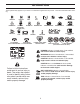
OPERATION These symbols may appear on your tractor or in literature supplied with the product. Learn and understand their meaning.
OPERATION KNOW YOUR TRACTOR READ THIS OWNER'S MANUAL AND SAFETY RULES BEFORE OPERATING YOUR TRACTOR Compare the illustrations with your tractor to familiarize yourself with the locations of various controls and adjustments. Save this manual for future reference. G P H D B N F E C J K A M L FIG. 3 Our tractors conform to the applicable safety standards of the American National Standards Institute. (H) LIGHT SWITCH – Turns the headlights on and off.
OPERATION The operation of any tractor can result in foreign objects thrown into the eyes, which can result in severe eye damage. Always wear safety glasses or eye shields while operating your tractor or performing any adjustments or repairs. We recommend standard safety glasses or a wide vision safety mask worn over spectacles. HOW TO USE YOUR TRACTOR TO SET PARKING BRAKE (See Fig. 4) Your tractor is equipped with an operator presence sensing switch.
OPERATION TO ADJUST GAUGE WHEELS (See Fig. 9) Gauge wheels are properly adjusted when they are slightly off the ground when mower is at the desired cutting height in operating position. Gauge wheels then keep the deck in proper position to help prevent scalping in most terrain conditions. NOTE: Adjust gauge wheels with tractor on a flat level surface. • Adjust mower to desired cutting height (See “TO ADJUST MOWER CUTTING HEIGHT” in this section of manual).
OPERATION TO TRANSPORT (See Figs. 3 and 11) REVERSE OPERATION SYSTEM (ROS) When pushing or towing your tractor, be sure to disengage transmission by placing freewheel control in freewheeling position. Free wheel control is located at the rear drawbar of tractor. • Raise attachment lift to highest position with attachment lift control. • Pull freewheel control out and down into the slot and release so it is held in the disengaged position. • Do not push or tow tractor at more than two (2) MPH.
OPERATION • ADD GASOLINE • Fill fuel tank to bottom of filler neck. Do not overfill. Use fresh, clean, regular unleaded gasoline with a minimum of 87 octane. (Use of leaded gasoline will increase carbon and lead oxide deposits and reduce valve life). Do not mix oil with gasoline. Purchase fuel in quantities that can be used within 30 days to assure fuel freshness. The attachments and ground drive can now be used.
OPERATION 4. Depress forward drive pedal to full forward position, hold for five (5) seconds and release pedal. Depress reverse drive pedal to full reverse position, hold for five (5) seconds and release pedal. Repeat this procedure three (3) times. 5. Shut- off engine and set parking brake. 6. Engage transmission by placing freewheel control in engaged position (See “TO TRANSPORT” in this section of manual). 7. Sitting in the tractor seat, start engine.
MAINTENANCE MAINTENANCE SCHEDULE BEFORE EACH USE EVERY 8 HOURS EVERY 25 HOURS EVERY 50 HOURS EVERY 100 HOURS EVERY SEASON BEFORE STORAGE Check Brake Operation Check Tire Pressure T Check Operator Presence & ROS Systems R A Check for Loose Fasteners C Check/Replace Mower Blades T Lubrication Chart 0 Check Battery Level R Clean Battery and Terminals 3 4 Check Transaxle Cooling Check Mower Levelness Check V-Belts Check Engine Oil Level Change Engine Oil (with oil filter) 1,2 Change Engine Oil (wi
MAINTENANCE TRACTOR BLADE CARE For best results mower blades must be sharp. Replace worn, bent or damaged blades. Always observe safety rules when performing any maintenance. BRAKE OPERATION CAUTION: Use only a replacement blade approved by the manufacturer of your tractor. Using a blade not approved by the manufacturer of your tractor is hazardous, could damage your tractor and void your warranty.
MAINTENANCE • • TO CHANGE ENGINE OIL (See Fig. 14 & 15) Determine temperature range expected before oil change. All oil must meet API service classification C. • Be sure tractor is on level surface. • Oil will drain more freely when warm. • Catch oil in a suitable container. • Remove oil fill cap/dipstick. Be careful not to allow dirt to enter the engine when changing oil. • Remove yellow cap from end of drain valve and install the drain tube onto the fitting. Rinse the battery with plain water and dry.
MAINTENANCE ENGINE OIL FILTER CLAMP Replace the engine oil filter every season or every other oil change if the tractor is used more than 100 hours in one year. CLAMP FUEL FILTER MUFFLER FIG. 16 Inspect and replace corroded muffler and spark arrester (if equipped) as it could create a fire hazard and/or damage. CLEANING • Clean engine, battery, seat, finish, etc. of all foreign matter. • Keep finished surfaces and wheels free of all gasoline, oil, etc.
SERVICE AND ADJUSTMENTS WARNING: TO AVOID SERIOUS INJURY, BEFORE PERFORMING ANY SERVICE OR ADJUSTMENTS: • Depress brake pedal fully and set parking brake. • Place attachment clutch in “DISENGAGED” position. • Turn ignition key to “STOP” and remove key. • Make sure the blades and all moving parts have completely stopped. • Disconnect spark plug wire from spark plug and place wire where it cannot come in contact with plug. TO REMOVE MOWER (See Fig.
SERVICE AND ADJUSTMENTS • A • tor. Insert rod end of link assembly through front hole in tractor front suspension bracket (F). Insert end of link (E) into hole in front mower bracket and secure with washer and retainer spring (J). Hook end of clutch cable spring (Q) into hole in idler E B • FIG. 18 on rear mower bracket and secure with washer and retainer spring. ATTACH FRONT LINK (E) - Work from left side of trac- J F H FIG. 20 arm (R).
SERVICE AND ADJUSTMENTS TO LEVEL MOWER 02966 Make sure tires are properly inflated to the PSI shown on tires. If tires are over or under inflated, it may affect the appearance of your lawn and lead you to think the mower is not adjusted properly. A A VISUAL SIDE-TO-SIDE ADJUSTMENT (See Fig. 22) • With all tires properly inflated and if your lawn appears unevenly cut, determine which side of mower is cutting lower. NOTE: As desired, you can raise the low side of mower or lower the high side.
SERVICE AND ADJUSTMENTS TO CHECK AND ADJUST BRAKE (See Fig. 27) TO REPLACE MOWER DRIVE BELT MOWER DRIVE BELT REMOVAL (See Fig. 26) • Park tractor on a level surface. Engage parking brake. Disengage attachment clutch control. • Remove screws from L.H. mandrel cover and remove cover. • Remove small retainer spring and lift clutch spring off pulley bolt. • Roll belt over the top of L.H. mandrel pulley. • Remove belt from engine pulley. • Remove belt from idler pulleys.
SERVICE AND ADJUSTMENTS TO REPLACE MOTION DRIVE BELT (See Fig. 28) FRONT WHEEL TOE-IN/CAMBER Your new tractor front wheel toe-in and camber is set at the factory and is normal. The front wheel toe-in and camber are not adjustable. If damage has occurred to affect the factory set front wheel toe-in or camber, contact a qualified service center. Park the tractor on level surface. Engage parking brake. For assistance, there is a belt installation guide decal on bottom side of left footrest.
SERVICE AND ADJUSTMENTS TO ATTACH JUMPER CABLES • Connect one end of the RED cable to the POSITIVE (+) terminal of each battery(A-B), taking care not to short against tractor chassis. • Connect one end of the BLACK cable to the NEGATIVE (-) terminal (C) of fully charged battery. • Connect the other end of the BLACK cable (D) to good chassis ground, away from fuel tank and battery.
STORAGE Immediately prepare your tractor for storage at the end of the season or if the tractor will not be used for 30 days or more. ENGINE FUEL SYSTEM IMPORTANT: IT IS IMPORTANT TO PREVENT GUM DEPOSITS FROM FORMING IN ESSENTIAL FUEL SYSTEM PARTS SUCH AS CARBURETOR, FUEL FILTER, FUEL HOSE, OR TANK DURING STORAGE. ALSO, EXPERIENCE INDICATES THAT ALCOHOL BLENDED FUELS (CALLED GASOHOL OR USING ETHANOL OR METHANOL) CAN ATTRACT MOISTURE WHICH LEADS TO SEPARATION AND FORMATION OF ACIDS DURING STORAGE.
TROUBLESHOOTING POINTS PROBLEM CAUSE CORRECTION Will not start 1. 2. 3. 4. 5. 6. 7. 8. 1. 2. 3. 4. 5. 6. 7. 8. Out of fuel. Engine not “CHOKED” properly. Engine flooded. Bad spark plug. Weak or dead battery. Dirty air filter. Dirty fuel filter. Water in fuel. 9. 10. Loose or damaged wiring. Carburetor out of adjustment. 9. 10. 11. Engine valves out of adjustment. 11. Fill fuel tank. See “TO START ENGINE” in Operation section. Wait several minutes before attempting to start. Replace spark plug.
TROUBLESHOOTING POINTS PROBLEM CAUSE CORRECTION Engine dies when tractor is shifted into reverse 1. 1. Turn ignition key to ROS "ON" position. See Operation section. Reverse operation system (ROS) is not "ON" while mower or other attachment is engaged. Engine continues to run when operator leaves seat with attachment clutch engaged 1. Faulty operator-safety presence control system. 1. Check wiring, switches and connections. If not corrected, contact an authorized service center/ department.
LIMITED WARRANTY The Manufacturer warrants to the original consumer purchaser that this product as manufactured is free from defects in materials and workmanship. For a period of two (2) years from date of purchase by the original consumer purchaser, we will repair or replace, at our option, without charge for parts or labor incurred in replacing parts, any part which we find to be defective due to materials or workmanship. This Warranty is subject to the following limitations and exclusions. 1.
SERVICE NOTES 28
SUGGESTED GUIDE FOR SIGHTING SLOPES FOR SAFE OPERATION FOL DA L O NG D THIS O I T S T A E D LIN 1 5 DEG E RE E S LOP E ONLY RIDE UP AND DOWN HILL, NOT ACROSS HILL 15 DEGREES MAX. WARNING: To avoid serious injury, operate your tractor up and down the face of slopes, never across the face. Do not mow slopes greater than 15 degrees. Make turns gradually to prevent tipping or loss of control. Exercise extreme caution when changing direction on slopes. 1. Fold this page along dotted line indicated above. 2.
PARTS AND SERVICE This product has been expertly engineered and carefully manufactured to rigid quality standards. As with all mechanical products, some adjustments or part replacement may be necessary during the life of your unit. For Parts and service, contact our authorized distributor: call 1-800-849-1297 • For replacement parts, have available the following information: a. Model Number/Manufacturer's I.D. Number b. Description of part.
PARTS AND SERVICE This product has been expertly engineered and carefully manufactured to rigid quality standards. As with all mechanical products, some adjustments or part replacement may be necessary during the life of your unit. For Parts and service, contact our authorized distributor: call 1-800-849-1297 • For replacement parts, have available the following information: a. Model Number/Manufacturer's I.D. Number b. Description of part.
1. Fold this page along dotted line indicated above. 2. Hold page before you so that its left edge is vertically parallel to a tree trunk or other upright structure. 3. Sight across the fold in the direction of hill slope you want to measure. 4. Compare the angle of the fold with the slope of the hill. WARNING: To avoid serious injury, operate your tractor up and down the face of slopes, never across the face. Do not mow slopes greater than 15 degrees.
SERVICE NOTES 28
LIMITED WARRANTY The Manufacturer warrants to the original consumer purchaser that this product as manufactured is free from defects in materials and workmanship. For a period of two (2) years from date of purchase by the original consumer purchaser, we will repair or replace, at our option, without charge for parts or labor incurred in replacing parts, any part which we find to be defective due to materials or workmanship. This Warranty is subject to the following limitations and exclusions.
TROUBLESHOOTING POINTS 1. Engine dies when tractor is shifted into reverse CAUSE PROBLEM Reverse operation system (ROS) is not "ON" while mower or other attachment is engaged. Faulty operator-safety presence control system. CORRECTION 1. 1. 2. 3. 4. 5. 6. 7. 8. 9. 10. 11. Poor grass discharge 1. 2. 3. 4. Obstruction in clutch mechanism. Worn/damaged mower drive belt. Frozen idler pulley. Frozen blade mandrel. 1. 2. 3. 4. Mower blades will not rotate 1. 2. 3. 4. 5. Worn, bent or loose blade.
TROUBLESHOOTING POINTS 1. 2. 3. 4. 5. 6. 7. 8. Will not start CAUSE PROBLEM Out of fuel. Engine not “CHOKED” properly. Engine flooded. Bad spark plug. Weak or dead battery. Dirty air filter. Dirty fuel filter. Water in fuel. Engine valves out of adjustment. 11. Loose or damaged wiring. Carburetor out of adjustment. 9. 10. Cutting too much grass/too fast. Throttle in “CHOKE” position. Build-up of grass, leaves and trash under mower. Dirty air filter. Low oil level/dirty oil. Faulty spark plug.
STORAGE Immediately prepare your tractor for storage at the end of the season or if the tractor will not be used for 30 days or more. WARNING: Never store the tractor with gasoline in the tank inside a building where fumes may reach an open flame or spark. Allow the engine to cool before storing in any enclosure. TRACTOR Remove mower from tractor for winter storage. When mower is to be stored for a period of time, clean it thoroughly, remove all dirt, grease, leaves, etc. Store in a clean, dry area.
SERVICE AND ADJUSTMENTS TO ATTACH JUMPER CABLES • Connect one end of the RED cable to the POSITIVE (+) terminal of each battery(A-B), taking care not to short against tractor chassis. • Connect one end of the BLACK cable to the NEGATIVE (-) terminal (C) of fully charged battery. • Connect the other end of the BLACK cable (D) to good chassis ground, away from fuel tank and battery. TO REMOVE CABLES, REVERSE ORDER • BLACK cable first from chassis and then from the fully charged battery.
SERVICE AND ADJUSTMENTS TO REPLACE MOTION DRIVE BELT (See Fig. 28) Park the tractor on level surface. Engage parking brake. For assistance, there is a belt installation guide decal on bottom side of left footrest. BELT REMOVAL • Remove mower (See “TO REMOVE MOWER” in this section of manual). NOTE: Observe entire motion drive belt and position of all belt guides and keepers. • Remove belt from stationary idler (A) and clutching idler (B). • Remove belt from centerspan idler (C).
SERVICE AND ADJUSTMENTS TO REPLACE MOWER DRIVE BELT MOWER DRIVE BELT REMOVAL (See Fig. 26) • Park tractor on a level surface. Engage parking brake. Disengage attachment clutch control. • Remove screws from L.H. mandrel cover and remove cover. • Remove small retainer spring and lift clutch spring off pulley bolt. • Roll belt over the top of L.H. mandrel pulley. • Remove belt from engine pulley. • Remove belt from idler pulleys.
SERVICE AND ADJUSTMENTS TO LEVEL MOWER Make sure tires are properly inflated to the PSI shown on tires. If tires are over or under inflated, it may affect the appearance of your lawn and lead you to think the mower is not adjusted properly. VISUAL SIDE-TO-SIDE ADJUSTMENT (See Fig. 22) • With all tires properly inflated and if your lawn appears unevenly cut, determine which side of mower is cutting lower. NOTE: As desired, you can raise the low side of mower or lower the high side.
• A SERVICE AND ADJUSTMENTS • • tor. Insert rod end of link assembly through front hole in tractor front suspension bracket (F). Insert end of link (E) into hole in front mower bracket and secure with washer and retainer spring (J). Hook end of clutch cable spring (Q) into hole in idler E B FIG. 18 on rear mower bracket and secure with washer and retainer spring. ATTACH FRONT LINK (E) - Work from left side of trac- J F H FIG. 20 arm (R).
SERVICE AND ADJUSTMENTS WARNING: TO AVOID SERIOUS INJURY, BEFORE PERFORMING ANY SERVICE OR ADJUSTMENTS: Depress brake pedal fully and set parking brake. Place attachment clutch in “DISENGAGED” position. Turn ignition key to “STOP” and remove key. Make sure the blades and all moving parts have completely stopped. Disconnect spark plug wire from spark plug and place wire where it cannot come in contact with plug. • • • • • TO REMOVE MOWER (See Fig.
ENGINE OIL FILTER MAINTENANCE Replace the engine oil filter every season or every other oil change if the tractor is used more than 100 hours in one year. CLAMP CLAMP FUEL FILTER MUFFLER Inspect and replace corroded muffler and spark arrester (if equipped) as it could create a fire hazard and/or damage. SPARK PLUGS Replace spark plugs at the beginning of each mowing season or after every 100 hours of operation, whichever occurs first.
• • • • MAINTENANCE Rinse the battery with plain water and dry. Clean terminals and battery cable ends with wire brush until bright. Coat terminals with grease or petroleum jelly. Reinstall battery (See “REPLACING BATTERY" in the SERVICE AND ADJUSTMENTS section of this manual). V-BELTS Check V-belts for deterioration and wear after 100 hours of operation and replace if necessary. The belts are not adjustable. Replace belts if they begin to slip from wear. TO CHANGE ENGINE OIL (See Fig.
TRACTOR MAINTENANCE BLADE CARE Always observe safety rules when performing any maintenance. BRAKE OPERATION If tractor requires more than five (5) feet to stop at highest speed in highest gear on a level, dry concrete or paved surface, then brake must be serviced. (See “TO CHECK BRAKE” in the Service and Adjustments section of this manual). For best results mower blades must be sharp. Replace worn, bent or damaged blades.
MAINTENANCE SCHEDULE MAINTENANCE BEFORE EACH USE EVERY 8 HOURS EVERY 25 HOURS EVERY 50 HOURS EVERY 100 HOURS EVERY SEASON BEFORE STORAGE Check Brake Operation Check Tire Pressure T Check Operator Presence & ROS Systems R A Check for Loose Fasteners C Check/Replace Mower Blades T Lubrication Chart 0 Check Battery Level R Clean Battery and Terminals 3 4 Check Transaxle Cooling Check Mower Levelness Check V-Belts Check Engine Oil Level Change Engine Oil (with oil filter) 1,2 Change Engine Oil (wi
OPERATION 4. Depress forward drive pedal to full forward position, hold for five (5) seconds and release pedal. Depress reverse drive pedal to full reverse position, hold for five (5) seconds and release pedal. Repeat this procedure three (3) times. 5. Shut- off engine and set parking brake. 6. Engage transmission by placing freewheel control in engaged position (See “TO TRANSPORT” in this section of manual). 7. Sitting in the tractor seat, start engine.
ADD GASOLINE • OPERATION • Fill fuel tank to bottom of filler neck. Do not overfill. Use fresh, clean, regular unleaded gasoline with a minimum of 87 octane. (Use of leaded gasoline will increase carbon and lead oxide deposits and reduce valve life). Do not mix oil with gasoline. Purchase fuel in quantities that can be used within 30 days to assure fuel freshness. CAUTION: Wipe off any spilled oil or fuel. Do not store, spill or use gasoline near an open flame.
OPERATION REVERSE OPERATION SYSTEM (ROS) Your tractor is equipped with a Reverse Operation System (ROS). Any attempt by the operator to travel in the reverse direction with the attachment clutch engaged will shut off the engine unless ignition key is placed in the ROS "ON" position. WARNING: Backing up with the attachment clutch engaged while mowing is strongly discouraged.
J K L FIG. 7 OPERATION TO ADJUST GAUGE WHEELS (See Fig. 9) SYSTEM CHARACTERISTICS The cruise control should only be used while mowing or transporting on relatively smooth, straight surfaces. Other conditions such as trimming at slow speeds may cause the cruise control to disengage. Do not use the cruise control on slopes, rough terrian or while trimmimg or turning.
OPERATION The operation of any tractor can result in foreign objects thrown into the eyes, which can result in severe eye damage. Always wear safety glasses or eye shields while operating your tractor or performing any adjustments or repairs. We recommend standard safety glasses or a wide vision safety mask worn over spectacles. HOW TO USE YOUR TRACTOR TO SET PARKING BRAKE (See Fig. 4) Your tractor is equipped with an operator presence sensing switch.
OPERATION KNOW YOUR TRACTOR READ THIS OWNER'S MANUAL AND SAFETY RULES BEFORE OPERATING YOUR TRACTOR Compare the illustrations with your tractor to familiarize yourself with the locations of various controls and adjustments. Save this manual for future reference. G P H D B N F E C J K A M L FIG. 3 Our tractors conform to the applicable safety standards of the American National Standards Institute. (H) LIGHT SWITCH – Turns the headlights on and off.
OPERATION These symbols may appear on your tractor or in literature supplied with the product. Learn and understand their meaning.
• • • ASSEMBLY Place freewheel control in "transmission disengaged position" (See “TO TRANSPORT” in the Operation section of this manual). Roll tractor forward off skid. Remove banding holding the deflector shield up against tractor. TO DRIVE TRACTOR OFF SKID (See Operation section for location and function of controls) • • • • • • • • • • Be sure all the above assembly steps have been completed. Check engine oil level and fill fuel tank with gasoline.
UNASSEMBLED PARTS Slope Sheet Key (1) Oil Drain Tube (2) Keys ASSEMBLY Your new tractor has been assembled at the factory with the exception of those parts left unassembled for shipping puposes. When right or left hand is mentioned in this manual, it means when you are in the operating position (seated behind the steering wheel). TO REMOVE TRACTOR FROM CARTON ADJUST SEAT (See Fig. 2) • • • Sit in seat.
PRODUCT SPECIFICATIONS 45-55FT. LBS. Blade Bolt Torque: AMP/HR: MIN. CCA: Case Size: Battery: 3 AMPS Battery 5 AMPS Headlights Charging System: Forward: Reverse: Ground Speed (MPH): Champion QC12YC (Gap: .040") Spark Plug: W/ Filter: W/O Filter: Oil Capacity: SAE 30 (above 32°F) SAE 5W-30 (below 32°F) Oil Type (API-SG-SL): 3 Gallons Unleaded Regular Gasoline Capacity and type: 64 oz 60 oz. 0 – 5.5 0 – 2.4 28 230 U1R CONGRATULATIONS on your purchase of a new tractor.
III. CHILDREN SAFETY RULES Safe Operation Practices for Ride-On Mowers Tragic accidents can occur if the operator is not alert to the presence of children. Children are often attracted to the machine and the mowing activity. Never assume that children will remain where you last saw them. • Keep children out of the mowing area and in the watchful care of a responsible adult other than the operator. • Be alert and turn machine off if a child enters the area.
SAFETY RULES Safe Operation Practices for Ride-On Mowers DANGER: THIS CUTTING MACHINE IS CAPABLE OF AMPUTATING HANDS AND FEET AND THROWING OBJECTS. FAILURE TO OBSERVE THE FOLLOWING SAFETY INSTRUCTIONS COULD RESULT IN SERIOUS INJURY OR DEATH. WARNING: In order to prevent accidental starting when setting up, transporting, adjusting or making repairs, always disconnect spark plug wire and place wire where it cannot contact spark plug.
IMPORTANT MANUAL Do Not Throw Away 03076 OPERATOR'S MANUAL MODEL: PB22H46YTX WARNING: Read this Manual and follow all Warnings and Safety Instructions. Failure to do so can result in serious injury. LAWN TRACTOR ALWAYS WEAR EYE PROTECTION DURING OPERATION Visit our website: www.poulan-pro.com Printed in U.S.A. 418774 12.13.