IMPORTANT MANUAL Do Not Throw Away OWNER'S MANUAL MODEL NUMBER: 961940007 SNOW THROWER WARNING: Read the Owner's Manual and follow all Warnings and Safety Instructions. Failure to do so can result in serious injury. Always Wear Eye Protection During Operation 421916 08.21.08 TH Printed in U.S.A.
IMPORTANT Safe Operation Practices for Walk-Behind Snow Throwers This snow thrower is capable of amputating hands and feet and throwing objects. Failure to observe the following safety instructions could result in serious injury. WARNING: Snow throwers have exposed rotating parts, which can cause severe injury from contact, or from material thrown from the discharge chute. Keep the area of operation clear of all persons, small children and pets at all times including startup.
6. When cleaning, repairing or inspecting the snow thrower, stop the engine and make certain the collector/impeller and all moving parts have stopped. Disconnect the spark plug wire and keep the wire away from the plug to prevent someone from accidentally starting the engine. 7. Do not run the engine indoors, except when starting the engine and for transporting the snow thrower in or out of the building. Open the outside doors; exhaust fumes are dangerous. 8.
PARTS PACKED SEPARATELY IN CARTON (1) FUEL STABILIZER PACKET (1) MULTIWRENCH (180684) (1) SAFTEY IGNITION KEY (193071) (1) POWER CORD (198563) (1) AUGER CONTROL ROD (1) TRACTION DRIVE CONTROL ROD (1) DISCHARGE CHUTE EXTRA SHEAR BOLTS AND NUTS (2) SHEAR BOLTS 1/4-20 x 1-3/4 (198636) (2) SPACERS (198638) (2) LOCKNUTS 1/4-20 (73800400) ROTATOR HEAD MOUNTING (3) RETAINER SPRINGS (169675) (1) WASHER 3/8 (19131316) (1) LOCKNUT 3/8 (73800600) CHUTE DEFLECTOR REMOTE CONTROL (1) LOCKNUT 5/16-18 (751153)
ASSEMBLY / PRE-OPERATION Read these instructions and this manual in its entirety before you attempt to assemble or operate your new snow thrower. Reading the entire manual will familiarize you with the unit, which will assist you in assembly, operation and maintenance of the product. Your new snow thrower has been assembled at the factory with the exception of those parts left unassembled for shipping purposes. All parts such as nuts, washers, bolts, etc.
ASSEMBLY / PRE-OPERATION INSTALL TRACTION DRIVE CONTROL ROD (See Figs. 3 and 4) The traction drive control rod has the long loop on the end of the spring as shown. 1. Slide rubber sleeve up rod and hook end of spring into pivot bracket with loop opening down as shown. 2. With top end of rod positioned under left side of control panel, push rod down and insert top end of rod into hole in drive control bracket. Secure with retainer spring. INSTALL AUGER CONTROL ROD (See Figs.
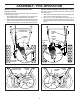
ASSEMBLY / PRE-OPERATION INSTALL CHUTE DEFLECTOR REMOTE CONTROL (See Figs. 8 and 9) 1. Install remote cable bracket to discharge chute with 5/16-18 carriage bolt and 5/16-18 locknut as shown. Tighten securely. 2. Install remote cable eyelet to chute deflector with 1/4-20 shoulder bolt, nylon friction washer and 1/4-20 locknut as shown. Tighten securely. 3. Install spring hooks between hex nuts on chute rotater head and into hole in chute deflector as shown.
OPERATION KNOW YOUR SNOW THROWER READ THIS OWNER'S MANUAL AND ALL SAFETY RULES BEFORE OPERATING YOUR SNOW THROWER. Compare the illustrations with your snow thrower to familiarize yourself with the location of various controls and adjustments. Save this manual for future reference. These symbols may appear on your snow thrower or in literature supplied with the product. Learn and understand their meaning.
OPERATION AUGER DISCHARGE CHUTE CONTROL LEVER CONTROL LEVER DEFLECTOR TRACTION DRIVE SPEED REMOTE RECOIL DRIVE CON TROL LEVER CONTROL (AUXILIARY) CONTROL LEVER STARTER LEVER HANDLE GASOLINE FILLER CAP ELECTRIC START BUTTON MUFFLER CHUTE DEFLECTOR CHOKE CONTROL LH TURN TRIGGER PRIMER SAFETY IGNITION KEY ON / OFF SWITCH DISCHARGE CHUTE LIGHT HANDLE KNOB CLEAN-OUT TOOL MUFFLER NOTE: ITEMS ABOVE ARE SHOWN IN THEIR TYPICAL LOCATION ON THE ENGINE.
OPERATION The operation of any snow thrower can result in foreign objects thrown into the eyes, which can result in severe eye damage. Always wear safety glasses or eye shields while operating your snow thrower or performing any adjustments or repairs. We recommend standard safety glasses or a wide vision safety mask worn over spectacles. The DIRECTION in which snow is to be thrown is controlled by the discharge chute control lever.
OPERATION TO MOVE FORWARD AND BACKWARD (See Fig. 15) SELF-PROPELLING, forward and reverse movement of the snow thrower, is controlled by the traction drive control lever located on the left side handle. • Squeeze traction drive control lever to handle to engage the drive system. • Release traction drive control lever to stop the forward or reverse movement of the snow thrower. SPEED and DIRECTION are controlled by the drive speed control lever.
OPERATION BEFORE STARTING THE ENGINE TO ADJUST SKID PLATES (See Fig. 17) NOTE: The wrench provided in your parts bag may be used to adjust the skid plates. Skid plates are located on each side of the auger housing and adjust the clearance between the scraper bar and the ground surface. Adjust skid plates evenly to proper height for current surface conditions.
OPERATION TO START ENGINE Your snow thrower engine is equipped with both a 120 Volt A.C. electric starter and a recoil starter. The electric starter is equipped with a three-wire power cord and plug and is designed to operate on 120 Volt A.C. household current. • Be sure your house is a 120 Volt A.C. three-wire grounded system. If you are uncertain, consult a licensed electrician. 6. When the engine starts, release the recoil starter handle and slowly move the choke control to the “OFF” position.
MAINTENANCE GENERAL RECOMMENDATIONS LUBRICATION CHART The warranty on this snow thrower does not cover items that have been subjected to operator abuse or negligence. To receive full value from the warranty, operator must maintain snow thrower as instructed in this manual. Some adjustments will need to be made periodically to properly maintain your snow thrower. All adjustments in the Service and Adjustments section of this manual should be checked at least once each season.
MAINTENANCE SNOW THROWER Always observe safety rules when performing maintenance. TIRES • Maintain proper air pressure in both tires (14–17 P.S.I. / 19-24.5 N-m). • Keep tires free of gasoline / oil, which can harm rubber. NOTE: To seal tire punctures and prevent flat tires due to slow leaks, tire sealant may be purchased from your local parts dealer. Tire sealant also prevents tire dry rot and corrosion.
SERVICE AND ADJUSTMENTS WARNING: To avoid serious injury, before performing any service or adjustments: 1. Be sure the on/off switch is in the OFF position. 2. Remove safety ignition key. 3. Make sure the augers and all moving parts have completely stopped. 4. Disconnect spark plug wire from spark plug and place wire where it cannot come in contact with plug. SNOW THROWER TO ADJUST SNOW THROWER HEIGHT See “TO ADJUST SKID PLATES” and “SCRAPER BAR” in the Operation section of this manual. 1.
SERVICE AND ADJUSTMENTS TO REPLACE BELTS (See Fig. 21) The auger and traction drive belts are not adjustable. If the belts are damaged or begin to slip from wear, they should be replaced. It is recommended that the belt(s) be replaced by a qualified service center. NOTE: It is recommended that both the auger and traction drive belt be replaced at the same time.
TO REMOVE WHEELS (See Fig. 22) • Remove the klik pin and remove wheel from axle. IMPORTANT: When installing wheel, be sure to use the axle hole closest to the end of the shaft – do not use the hole in the wheel hub (if equipped). Inner hole in axle and hole in wheel hub are not used for your model snow thrower. KLIK PIN (INSTALL IN OUTER HOLE OF AXLE ONLY) OUTER HOLE AXLE WHEEL HUB WHEEL FIG.
TROUBLESHOOTING See appropriate section in manual unless directed to an authorized service centre/department. PROBLEM Does not start CAUSE 1. Fuel shut-off valve (if so equipped) in OFF position. 2. Safety ignition key is not inserted. 3. Out of fuel. 4. Throttle in STOP position (or ON/OFF switch is OFF). 5. Choke in OFF position. 6. Primer not depressed. 7. Engine is flooded. 8. Spark plug wire is disconnected. 9. Bad spark plug. 10. Stale fuel. 11. Water in fuel. CORRECTION 1.
REPAIR PARTS SNOW THROWER - MODEL 961940007 (96194000701) AUGER HOUSING / IMPELLER ASSEMBLY 5 11 11 6 7 15 14 16 12 13 8 11 4 12 3 17 10 11 1 9 2 33 32 34 30 31 31 26 36 29 28 27 23 22 21 20 25 35 24 23 22 2 (EXPLODED) 21 18 19 01.07.
REPAIR PARTS SNOW THROWER - MODEL 961940007 (96194000701) AUGER HOUSING / IMPELLER ASSEMBLY KEY NO. 1 2 3 4 5 6 7 8 9 10 11 12 13 14 15 16 17 18 19 20 21 22 23 24 25 26 27 28 29 30 31 32 33 34 35 36 PART NO.
REPAIR PARTS SNOW THROWER - MODEL 961940007 (96194000701) AUGER HOUSING / IMPELLER ASSEMBLY 1 3 (5x) 4 (5x) 2 01.07.003-A KEY NO. 1 2 3 4 PART NO. 404930X428 404933X479 72270505 155377 DESCRIPTION AUGER HOUSING SCRAPPER BAR CARRIAGE BOLT 5/16−18 X .625 NUT 5/16−18 2 KEY NO. 1 2 1 PART NO. 420497X479 420498X479 DESCRIPTION AUGER ASSEMBLY 30 LH AUGER ASSEMBLY 30 RH 01.07.019-A NOTE: All component dimensions given in U.S. inches. 1 inch = 25.
REPAIR PARTS SNOW THROWER - MODEL 961940007 (96194000701) AUGER HOUSING / IMPELLER ASSEMBLY 3 4 2 4 01.11.001-A 3 KEY NO. 1 2 3 4 PART NO. 174762X479 178777X479 72270506 751153 DESCRIPTION SKID PLATE LH SKID PLATE RH CARRIAGE BOLT 5/16−18 X .75 NUT 5/16−18 1 2 3 1 1 2 3 01.07.024-B KEY NO. PART NO. DESCRIPTION 1 2 3 420478 411939 179582 AUGER BEARING BEARING PLUG SCREW 5/16−18 X 1.00 NOTE: All component dimensions given in U.S. inches. 1 inch = 25.
REPAIR PARTS SNOW THROWER - MODEL 961940007 (96194000701) CONTROL PANEL / DISCHARGE CHUTE 5 7 3 14 15 *13 *10 *9 2 KEY NO. 1 2 3 4 5 6 7 *8 *9 *10 *11 *12 *13 14 15 PART NO. 404770X428 178633X428 420673 420325 414280 128415 17501010 179829 179246 191730 72250505 751153 184505 420679 420672 4 DESCRIPTION CHUTE WELDMENT 6 DEFLECTOR WELDMENT DEFLECTOR CONTROL ASSEMBLY DEFLECTOR SEAL 1 KNOB BLACK POP RIVET SCREW 10−24 X .625 SHOULDER SCREW PLASTIC WASHER NUT 1/4−20 CARRIAGE BOLT 5/16−18 X .
REPAIR PARTS SNOW THROWER - MODEL 961940007 (96194000701) CONTROL PANEL / DISCHARGE CHUTE 2 2 1 *3 *6 *6 KEY NO. 1 2 *3 *4 *5 *6 PART NO. 420337 17501010 420678 420677 420675 420674 DESCRIPTION LEVER/CABLE ROTATOR ASSEMBLY SCREW 10−24 X .625 ROTATOR HEAD ROTATOR PIVOT BRACKET PULLEY PIVOT CABLE ASSEMBLY *4 01.09.007-A *5 NOTES: 1. ITEMS INDICATED WITH AN * ARE LISTED AS REFERENCE FOR SERVICE PARTS ONLY. 2 01.15.005-A 1 KEY NO. 1 2 PART NO.
SNOW THROWER - MODEL 961940007 (96194000701) REPAIR PARTS HANDLES 3 5 3 5 5 KEY NO. 1 2 3 4 5 PART NO. 419798X479 419799 X479 74780524 74780528 751153 DESCRIPTION LOOP HANDLE LH LOOP HANDLE RH SCREW 5/16−18 X 1.50 SCREW 5/16−18 X 1.75 NUT 5/16−18 KEY NO. 1 2 3 4 5 6 PART NO. 412675X004 414572 178831 169675 17060410 421252X004 DESCRIPTION INTERLOCK SPRING INTERLOCK CAM TORSION SPRING RETAINER SCREW 1/4−20 X .625 INTERLOCK STOP 1 3 5 4 2 01.08.004-A 4 3 2 5 1 6 01.08.
SNOW THROWER - MODEL 961940007 (96194000701) REPAIR PARTS HANDLES 10 2 11 8 4 7 9 9 5 6 7 1 3 13 8 12 13 14 14 12 KEY NO. 1 2 3 4 5 6 7 8 9 10 11 12 13 14 PART NO. 412683X479 412681X479 412682X479 412679X008 420889X008 412677 412680 169675 17060408 414280 414281 178899 19131316 72120618 01.08.002-D DESCRIPTION CONTROL PANEL CONTROL LEVER LH CONTROL LEVER RH TRACTION ROD ARM IMPELLER ROD ARM INTERLOCK ROD SPACER RETAINER SCREW 1/4−20 X .
SNOW THROWER - MODEL 961940007 (96194000701) REPAIR PARTS HANDLES 2 KEY NO. 1 2 3 4 5 6 7 8 9 10 1 3 8 9 PART NO. 180480 405740 180445 187716 180447 178669 180926 72270506 155377 169675 DESCRIPTION IMPELLER ROD ASSEMBLY TRACTION ROD ASSEMBLY SHIFTER ROD TOP SHIFTER ROD BOTTOM SPRING SLEEVE IMPELLER SPRING TRACTION SPRING CARRIAGE BOLT 5/16−18 X .75 NUT 5/16−18 RETAINER 4 5 7 10 5 6 01.12.001-A NOTE: All component dimensions given in U.S. inches. 1 inch = 25.
SNOW THROWER - MODEL 961940007 (96194000701) REPAIR PARTS HANDLES 1 KEY NO. 1 2 3 4 2 PART NO. 419797X479 405784X479 150078 17000616 DESCRIPTION LOWER HANDLE PIVOT SUPPORT WELDMENT SCREW 5/16−18 X .750 SCREW 3/8−16 X 1.00 4 3 4 4 4 3 01.05.002-B 7 4 5 3 2 6 4 5 01.10.007-B 1 KEY NO. PART NO. DESCRIPTION 1 2 3 4 5 6 7 182906 178668 180927 184471 175262 178770 183784 CONSOLE PANEL HEADLIGHT BEZEL FLOOD HEADLIGHT SHOULDER SCREW 10−24 X .625 SCREW 10−24 X 1.
SNOW THROWER - MODEL 961940007 (96194000701) REPAIR PARTS DRIVE ITEM 43 EXPLODED 2 69 68 16 1 71 17 18 15 11 9 9 10 8 7 12 9 14 70 15 20 11 76 13 72 22 76 4 34 76 73 24 19 11 23 75 21 6 24 5 33 23 76 3 28 26 29 30 31 33 32 35 35 50 39 36 76 27 24 26 47 37 4 38 24 76 25 49 48 43 44 40 42 41 49 51 52 53 45 46 23 74 62 61 63 64 59 40 30 49 51 57 58 67 4 01.02.
REPAIR PARTS DRIVE SNOW THROWER - MODEL 961940007 (96194000701) KEY NO. PART NO. DESCRIPTION KEY NO. PART NO.
SNOW THROWER - MODEL 961940007 (96194000701) REPAIR PARTS DRIVE 6 7 1b 8 4 3 1b 7 1a 2 3 5 4 6 01.03.002-A KEY NO. PART NO. DESCRIPTION 1 1a 1b 2 3 4 5 6 7 8 404923 404307 9465M1 402691 174697 179830 146315 17490508 155443 189282 AXLE ASSEMBLY (assy of 1a,1b) AXLE SHAFT ROLL PIN 3/16 X 1.50 SPROCKET THRUST WASHER BEARING SCREW 5/16−18 X .625 SCREW 5/16−18 X .500 KLIK PIN 1/4 X 1.50 SQUARE KEY NOTE: All component dimensions given in U.S. inches. 1 inch = 25.
REPAIR PARTS SNOW THROWER - MODEL 961940007 (96194000701) CHASSIS / ENGINE / PULLEYS 4 2 3 4 3 1 01.00.006-A KEY NO. PART NO. DESCRIPTION -1 2 3 4 -----409346X428 417015X428 150406 150078 B&S ENGINE MODEL 20M314-0927-E1 FRAME WELDMENT ENGINE MOUNT PLATE ENGINE BOLT 3/8−16 SCREW 5/16−18 X .750 NOTE: All component dimensions given in U.S. inches. 1 inch = 25.4 mm IMPORTANT: Use only Original Equipment Manufacturer (O.E.M.) replacement parts.
REPAIR PARTS SNOW THROWER - MODEL 961940007 (96194000701) CHASSIS / ENGINE / PULLEYS 1 KEY NO. 1 2 3 4 2 PART NO. 192213 179157 419744 408007 DESCRIPTION BELT COVER IMPELLER PULLEY TRACTION BELT IMPELLER BELT 3 4 01.04.019-A NOTE: All component dimensions given in U.S. inches. 1 inch = 25.4 mm IMPORTANT: Use only Original Equipment Manufacturer (O.E.M.) replacement parts. Failure to do so could be hazardous, damage your snow thrower and void your warranty.
SNOW THROWER - MODEL 961940007 (96194000701) REPAIR PARTS WHEELS 2 17 20 16 18 15 18 24 17 16 20 19 2 3 2 1 4 5 6 23 22 23 19 7 8 9 7 22 11 21 21 11 10 4 14 12 13 13 14 10 9 6 3 5 8 12 01.15.001-A KEY NO. 1 2 3 4 5 6 7 8 9 10 11 12 13 14 15 16 17 18 19 20 21 22 23 24 PART NO.
SNOW THROWER - MODEL 961940007 (96194000701) REPAIR PARTS WHEELS 3 KEY NO. 1 2 3 PART NO. 410293 410294 17060410 DESCRIPTION CABLE BRACKET LH CABLE BRACKET RH SCREW 1/4−20 X .625 KEY NO. 1 2 PART NO. 192092X421 192093X421 DESCRIPTION WHEEL 16 X 4.80 X LH WHEEL 16 X 4.80 X RH 1 2 01.15.003-A 1 2 01.06.005-A NOTE: All component dimensions given in U.S. inches. 1 inch = 25.4 mm IMPORTANT: Use only Original Equipment Manufacturer (O.E.M.) replacement parts.
SNOW THROWER - MODEL 961940007 (96194000701) REPAIR PARTS BAG OF PARTS 4 6 5 7 9 8 3 10 2 1 11 14 KEY NO. PART NO. DESCRIPTION 1 2 3 4 5 6 7 8 9 10 11 12 13 14 198563 169675 180684 184505 179829 179246 191730 72250505 751153 73800600 19131316 198636 198638 73800400 POWER CORD RETAINER PIN WRENCH REMOTE SPRING SHOULDER BOLT 1/4−20 NYLON WASHER 1/4−20 LOCKNUT 1/4−20 CARRIAGE BOLT 5/16−18 X 5/8 LOCKNUT 5/16−18 LOCKNUT 3/8−16 WASHER 3/8 SHEAR BOLT 1/4−20 X 1−3/4 SPACER LOCKNUT 1/4−20 KEY NO.
SNOW THROWER - MODEL 961940007 (96194000701) REPAIR PARTS DECALS 1 2 4 9 12 6 5 1 10 11 3 KEY PART NO. NO.
SERVICE NOTES 39
LIMITED WARRANTY The Manufacturer warrants to the original consumer purchaser that this product as manufactured is free from defects in materials and workmanship. For a period of two (2) years from date of purchase by the original consumer purchaser, we will repair or replace, at our option, without charge for parts or labor incurred in replacing parts, any part which we find to be defective due to materials or workmanship. This Warranty is subject to the following limitations and exclusions. 1.