IMPORTANT MANUAL Do Not Throw Away • Español, p. 19 OWNER'S MANUAL MODEL NUMBER: 96194000506 SNOW THROWER WARNING: Read the Owner's Manual and follow all Warnings and Safety Instructions. Failure to do so can result in serious injury. Always Wear Eye Protection During Operation 424027 10.03.08 SR Printed in U.S.A.
IMPORTANT Safe Operation Practices for Walk-Behind Snow Throwers This snow thrower is capable of amputating hands and feet and throwing objects. Failure to observe the following safety instructions could result in serious injury. WARNING: Snow throwers have exposed rotating parts, which can cause severe injury from contact, or from material thrown from the discharge chute. Keep the area of operation clear of all persons, small children and pets at all times including startup.
6. When cleaning, repairing or inspecting the snow thrower, stop the engine and make certain the collector/impeller and all moving parts have stopped. Disconnect the spark plug wire and keep the wire away from the plug to prevent someone from accidentally starting the engine. 7. Do not run the engine indoors, except when starting the engine and for transporting the snow thrower in or out of the building. Open the outside doors; exhaust fumes are dangerous. 8.
PARTS PACKED SEPARATELY IN CARTON (1) AUGER CONTROL ROD (1) TRACTION DRIVE CONTROL ROD (1) MULTIWRENCH (180684) (2) FLAT WASHERS (1) DISCHARGE CHUTE (1) POWER CORD (198563) (3) RETAINER SPRINGS (169675) ROTATOR HEAD MOUNTING (2) CARRIAGE BOLTS 3/8-16 x 2.
ASSEMBLY / PRE-OPERATION HOW TO SET UP YOUR SNOW THROWER INSTALL SPEED CONTROL ROD (See Figs. 1 and 2) 1. Remove plastic tie securing rod to lower handle. 2. Insert rod into speed control bracket and secure with retainer spring. TOOL BOX (See Fig. 8) A toolbox is provided on your snow thrower. The toolbox is located on top of the belt cover. Store the extra shear bolts, nuts and multi-wrench provided in parts bag in the toolbox.
ASSEMBLY / PRE-OPERATION INSTALL AUGER CONTROL ROD (See Figs. 5 and 6) The auger control rod has the short loop on the end of the spring as shown. 1. Slide rubber sleeve up rod and hook end of spring into control arm with loop opening up as shown. 2. With top end of rod positioned under right side of control panel, push down on rod and insert end of rod into hole in auger control bracket. Secure with retainer spring. INSTALL DISCHARGE CHUTE / CHUTE ROTATOR HEAD (See Fig.
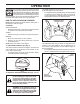
OPERATION KNOW YOUR SNOW THROWER READ THIS OWNER'S MANUAL AND ALL SAFETY RULES BEFORE OPERATING YOUR SNOW THROWER. Compare the illustrations with your snow thrower to familiarize yourself with the location of various controls and adjustments. Save this manual for future reference. These symbols may appear on your snow thrower or in literature supplied with the product. Learn and understand their meaning.
OPERATION AUGER DEFLECTOR REMOTE CONTROL CONTROL LEVER LEVER RECOIL DRIVE SPEED (AUXILIARY) CONTROL LEVER STARTER HANDLE GASOLINE FILLER CAP ELECTRIC START BUTTON MUFFLER CHUTE DEFLECTOR CHOKE CONTROL LIGHT PRIMER SAFETY IGNITION KEY TRACTION DRIVE CONTROL LEVER ON / OFF SWITCH DISCHARGE CHUTE CONTROL KNOB DISCHARGE CHUTE HANDLE KNOB CLEAN-OUT TOOL MUFFLER NOTE: ITEMS ABOVE ARE SHOWN IN THEIR TYPICAL LOCATION ON THE ENGINE. ACTUAL LOCATION MAY VARY WITH THE ENGINE ON YOUR UNIT.
OPERATION The operation of any snow thrower can result in foreign objects thrown into the eyes, which can result in severe eye damage. Always wear safety glasses or eye shields while operating your snow thrower or performing any adjustments or repairs. We recommend standard safety glasses or a wide vision safety mask worn over spectacles. The DIRECTION in which snow is to be thrown is controlled by the discharge chute control lever.
OPERATION TO THROW SNOW (See Fig. 12) The auger rotation is controlled by the auger control lever located on the right side handle. • Squeeze auger control lever to handle to engage the auger and throw snow. • Release the auger control lever to stop throwing snow. DISCHARGE CHUTE CLEAN-OUT TOOL AUGER CONTROL LEVER MOUNTING CLIP FIG. 13 TO MOVE FORWARD AND BACKWARD (See Fig.
OPERATION ADD GASOLINE (See Fig. 16) • Fill fuel tank to bottom of tank filler neck. Do not overfill. Use fresh, clean, regular unleaded gasoline with a minimum of 87 octane. Do not mix oil with gasoline. Purchase fuel in quantities that can be used within 30 days to assure fuel freshness. TO ADJUST SKID PLATES (See Fig. 15) NOTE: The wrench provided in your parts bag may be used to adjust the skid plates.
OPERATION TO START ENGINE Your snow thrower engine is equipped with both a 120 Volt A.C. electric starter and a recoil starter. The electric starter is equipped with a three-wire power cord and plug and is designed to operate on 120 Volt A.C. household current. • Be sure your house is a 120 Volt A.C. three-wire grounded system. If you are uncertain, consult a licensed electrician. 5. Pull recoil starter handle quickly. Do not allow starter rope to snap back. 6.
MAINTENANCE GENERAL RECOMMENDATIONS The warranty on this snow thrower does not cover items that have been subjected to operator abuse or negligence. To receive full value from the warranty, operator must maintain snow thrower as instructed in this manual. Some adjustments will need to be made periodically to properly maintain your snow thrower. All adjustments in the Service and Adjustments section of this manual should be checked at least once each season.
MAINTENANCE AUGER GEAR CASE • The gear case was filled with lubricant to the proper level at the factory. The only time the lubricant needs attention is if service has been performed on the gear case. • If lubricant is required, use only Ronex ED #1 grease. • Oil will drain more freely when warm. • Catch oil in a suitable container. NOTE: The left side wheel may be removed from snow thrower for easier access to the oil drain plug and placement of a suitable container.
SERVICE AND ADJUSTMENTS WARNING: To avoid serious injury, before performing any service or adjustments: 1. Be sure the on/off switch is in the OFF position. 2. Remove safety ignition key. 3. Make sure the augers and all moving parts have completely stopped. 4. Disconnect spark plug wire from spark plug and place wire where it cannot come in contact with plug. SNOW THROWER 3. Align holes in impeller hub with holes in impeller shaft and install two (2) new 1/4-20 x 1-5/8" capscrew/shear bolts.
SERVICE AND ADJUSTMENTS 8. RELIEVE TENSION ON TRACTION DRIVE BELT IDLER and remove traction drive belt from around pulleys. HINT: Insert a 3/8" drive ratchet (in the “ON” position) into the square hole in idler arm and rotate ratchet clockwise to relieve tension. 9. With tension relieved on idler, install new traction drive belt around pulleys and inside belt keepers. 10. Install clutch rod in swing plate; secure with hairpin. 11. Place auger belt around and inside the groove of auger pulley only. 12.
SERVICE AND ADJUSTMENTS TO REMOVE WHEELS (See Fig. 20) • Remove the klik pin and remove wheel from axle. IMPORTANT: When installing wheel, be sure to use the innermost hole in axle and the wheel hub hole. To disengage drive system from the wheels (for pushing or transporting the snow thrower), remove klik pin from wheel hub and insert pin into the outermost hole in axle only.
STORAGE OTHER • • • • • If possible, store your snow thrower indoors and cover it to protect it from dust and dirt. • Cover your snow thrower with a suitable protective cover that does not retain moisture. Do not use plastic. Plastic cannot breathe, which allows condensation to form and will cause your snow thrower to rust. IMPORTANT: Never cover snow thrower while engine/ exhaust area is still warm. Remove safety ignition key; store it in a safe place.
IMPORTANTE Procedimientos de Funcionamiento Seguro Para Máquinas Quitanieves Esta máquina puede amputar manos y pies y lanzar objetos. El no observar las siguientes instrucciones de seguridad puede dar lugar a heridas graves. ADVERTENCIA: Las máquinas quitanieves tienen partes giratorias expuestas, que pueden causar heridas graves por contacto, o por material lanzado desde el conducto de eyección.
4. Si la unidad empezara a vibrar de manera anormal, parar el motor y controlar inmediatamente para detectar la causa. Las vibraciones son generalmente indicio de problemas. 5. Parar el motor cada vez que se abandone la posición de funcionamiento, antes de limpiar el alojamiento del colector / impulsor o el conducto de eyección y cuando se hagan reparaciones, regulaciones o inspecciones. 6.
PARTES EMPACADAS POR SEPARADO EL LA CAJA DE CARTÓN (1) BIELA DE MANDO DE TALADRO (1) BIELA DE MANDO DE TRACCIÓN (1) MULTILLAVE (180684) (1) CONDUCTO LA DESCARGA (2) ARANDELAS PLANAS (1) CABLE DE ALIMENTACIÓN (198563) (3) RESORTES DE RETENCIÓN (169675) SOPORTE DE CABEZA GIRATORIA (1) ARANDELA 3/8 (19131316) (1) TUERCA DE SEGURIDAD 3/8 (73800600) (1) LLAVES DE IGNICIÓN DE SEGURIDAD (193071) PERNOS Y TURCAS EXTRA PARA LA CIZALLA (2) TORNIOLLOS DE CASQUILLO 1/4-20 x 1-3/4 (198636) (2) COCHE CIERRA 3
MONTAJE / PRE-OPERACIÓN COMO PREPARAR SU MÁQUINA QUITANIEVES 2. Montar la biela en el soporte del control de velocidad y apretar con el resorte de sujeción. PORTAHERRAMIENTAS (Ver Fig. 8) MONTAJE DE LA BIELA DE MANDO DE LA TRACCIÓN (Ver Figs. 3 y 4) Con su máquina quitanieves se le proporciona un portaherramientas. El portaherramientas está situado sobre la cubierta de la correa. Guarde los pernos de cizalla de recambio, tuercas y llave de tuercas en la bolsa de partes del portaherramientas.
MONTAJE / PRE-OPERACIÓN MONTAR LA BIELA DE MANDO DE LA BARRENA (Ver Figs. 5 y 6) MONTAR EL CONDUCTO DE EYECCIÓN / CABEZA GIRATORIA DEL CONDUCTO (Ver Fig. 7) La biela del mando de tracción tiene un gancho corto en la extremidad del resorte, como mostrado. 1. Deslizar el manguito de caucho sobre la biela y enganchar la terminación del resorte al brazo de mando con el gancho abierto hacia arriba como mostrado. 2.
OPERACIÓN FAMILIARÍCESE CON SU MÁQUINA QUITANIEVES LEA ESTE MANUAL DEL DUEÑO Y LAS REGLAS DE SEGURIDAD ANTES DE OPERAR SU MÁQUINA QUITANIEVES. Compare las ilustraciones con su segadora para familiarizarse con la ubicación de los diversos controles y ajustes. Guarde este manual para referencia en el futuro. Estos símbolos pueden apareser sobre su máquina quitanieves o en la literatura proporcionada con el producto. Aprenda y comprenda sus significados.
OPERACIÓN MANGO DE RETROCESO DE ARRANQUE PALANCA DE PALANCA DE CONTROL DE CONTROL LA BARRENA DE LA VELOCIDAD MANGO DE DE GUÍA RETROCESO (AUXILIAR) DE ARRANQUE TAPA DEL DEPOSITO DE GASOLINA SILENCIADOR CONTROL DE LA ESTRANGULACIÓN PALANCA DE PALANCA DE CONTROL DEL CONTROL CONDUCTO DE DE LA EYECCIÓN TRACCIÓN LUZ CEBADOR DEFLECTOR DE DESCARGA LLAVE DE ENCENDIDO DE SEGURIDAD INTERRUPTOR DE ON / OFF CONDUCTO DE DESCARGA POMO DE CONTROL DEL DEFLECTOR A DISTANCIA MANILLA DEL MANGO HERRAMIENTA PARA LIMPIAR
OPERACIÓN La operación de cualquier máquina quitanieves puede hacer que salten objetos extraños dentro de sus ojos, lo que puede producir daños graves en éstos. Siempre use anteojos de seguridad o protección para los ojos mientras opere su máquina quitanieves o cuando haga ajustes o reparaciones. Recomendamos gafas o una mascara de seguridad de visión amplia de seguridad usada sobre las gafas.
OPERACIÓN LANZAR LA NIEVE (Ver Fig. 12) GOULOTTE D’ÉVACUATION La rotación de la barrena se controla con la palanca de mando de la barrena posicionada en la empuñadura derecha. • Apretar la palanca de mando de la barrena hacia la empuñadura para conectar la barrena y lanzar nieve. • Soltar la palanca de mando de la barrena para parar de lanzar nieve. L’OUTIL DE NETTOYAGE SUPPORT DE MONTAGE À ATTACHE PALANCA DE CONTROL DE LA BARRENA FIG. 13 MOVERSE ADELANTE Y ATRÁS (Ver Fig.
OPERACIÓN REGULAR LAS PLACAS DE DESLIZAMIENTO (Ver Fig. 15) NOTA: la llave de apriete proporcionada en su bolsa de partes puede utilizarse para regular las placas de deslizamiento. Las placas de deslizamiento están posicionadas a cada lado del alojamiento de la barrena y regulan la distancia entre la barra de arrastre y el suelo. Regule las placas de deslizamiento uniformemente a la altura apropiada a las condiciones de la superficie.
OPERACIÓN • Asegúrese que la instalación eléctrica de su casa sea un sistema de tres hilos puesta a tierra de 120 Voltios A.C. Si no está seguro, consulte un electricista autorizado. Dejar que el motor se caliente por algunos minutos. El motor no proporcionará la plena potencia hasta que no haya alcanzado la temperatura normal de funcionamiento.
• Mantener el motor limpio y libre de nieve durante el uso. Esto ayudará a hacer pasar aire y prolongará la vida del motor. • Después de completar el trabajo de despejar nieve, dejar que el motor gire por algunos minutos para derretir nieve y hielo que puedan estar en el motor. • Limpiar a fondo toda la máquina quitanieves después de cada uso y secarla para que esté lista para el próximo uso. ADVERTENCIA: No hacer funcionar la máquina quitanieves si las condiciones del tiempo deterioran la visibilidad.
MANTENAMIENTO CORREAS EN V Controlar el deterioro y el desgaste de las correas en V después de 50 horas de funcionamiento y sustituir si fuera necesario. Las correas no se pueden regular. Sustituir las correas si empiezan a resbalar debido al desgaste. (Ver “ QUITAR EL CUBRE CORREAS” en la sección Mantenimiento y Regulaciones de este manual). Las correas en V de su quitanieve tienen una construcción especial y han de ser sustituidos con correas originales (OEM) disponibles en su revendedor más cercano.
SERVICIO Y ADJUSTES ADVERTENCIA: Para evitar lesiónes serias, antes de dar calquier servico o de hacer ajustes: 1. Asegurarse el interruptor de ON/OFF esté en posición OFF. 2. Quitar la llave de encendido de seguridad. 3. Asegúrese que la barrenas y que todas las partes movibles se hayan detenido completamente. 4. Desconecte el alambre de la bujía y póngalo en donde no pueda entrar en contacto con ésta.
SERVICIO Y ADJUSTES SUSTITUIR LAS CORREAS (Vea Fig. 19) 8. AFLOJAR EL TENSOR DE LA CORREA DE TRACCIÓN y desmontar la correa de tracción de alrededor de las poleas de transmisión. Las correas de la barrena y de la tracción no se pueden regular. Si las correas están dañadas o empiezan a resbalar por el desgaste, se tendrían que sustituir. Se recomienda que la(s) correa(s) sean sustituidas por el Centro de Piezas y Reparación.
DESMONTAR LAS RUEDAS (Ver Fig. 20) • Desmontar el perno de lingüete y desmontar la rueda del eje. IMPORTANTE: Cuando se instala la rueda, asegurarse de usar el orificio más interno en el eje y el orificio del cubo de la rueda. Para desconectar el sistema de mando de las ruedas (para empujar o transportar el quitanieve), quitar el perno de lingüete del cubo de la rueda e introducir el perno en el orificio de más externo del eje.
IDENTIFICACION DE PROBLEMAS Vea la sección apropiada en el manual amenos que esté dirigido a un centro de asistencia calificado. PROBLEMA No arranca CAUSA CORRECCIÓN 1. Válvula del combustible está OFF. 2. La llave de encendido de seguridad no está puesta. 3. Sin combustible. 4. Acelerador en posición de STOP (o interruptor de ON / OFF está OFF). 5. Obturador en posición OFF. 6. El cebador no está presionado. 1. Gire a la válvula del combustible a la posición ON. 2.
REPAIR PARTS SNOW THROWER - MODEL NUMBER 96194000506 AUGER HOUSING / IMPELLER ASSEMBLY 5 11 11 6 7 15 14 16 12 13 8 11 4 12 3 17 10 11 1 9 2 33 32 34 30 31 31 26 36 29 28 27 23 22 21 20 25 35 24 23 22 2 (EXPLODED) 21 18 19 01.07.004-B NOTE: All component dimensions given in U.S. inches. 1 inch = 25.4 mm IMPORTANT: Use only Original Equipment Manufacturer (O.E.M.) replacement parts. Failure to do so could be hazardous, damage your snow thrower and void your warranty.
REPAIR PARTS SNOW THROWER - MODEL NUMBER 96194000506 AUGER HOUSING / IMPELLER ASSEMBLY KEY NO. PART NO.
REPAIR PARTS SNOW THROWER - MODEL NUMBER 96194000506 AUGER HOUSING / IMPELLER ASSEMBLY 1 KEY NO. 1 2 3 4 PART NO. 404928X428 404931X479 72270505 155377 DESCRIPTION AUGER HOUSING SCRAPPER BAR CARRIAGE BOLT 5/16−18 X .625 NUT 5/16−18 KEY NO. 1 2 PART NO. 420493X479 420494X479 DESCRIPTION AUGER ASSEMBLY LH 24 AUGER ASSEMBLY RH 24 3 (5x) 4 (5x) 2 01.07.001-A 2 1 01.07.017-A NOTE: All component dimensions given in U.S. inches. 1 inch = 25.4 mm IMPORTANT: Use only Original Equipment Manufacturer (O.E.
REPAIR PARTS SNOW THROWER - MODEL NUMBER 96194000506 AUGER HOUSING / IMPELLER ASSEMBLY 2 3 1 1 KEY NO. 1 2 3 2 PART NO. 420478 411939 179582 DESCRIPTION AUGER BEARING BEARING PLUG SCREW 5/16−18 X 1.00 3 01.07.024-B 3 4 2 4 3 01.11.001-A 1 KEY NO. PART NO. DESCRIPTION 1 2 3 4 174762X479 178777X479 72270506 751153 SKID PLATE LH SKID PLATE RH CARRIAGE BOLT 5/16−18 X .75 NUT 5/16−18 NOTE: All component dimensions given in U.S. inches. 1 inch = 25.
REPAIR PARTS SNOW THROWER - MODEL NUMBER 96194000506 CONTROL PANEL / DISCHARGE CHUTE 2 11 10 5 8 3 6 9 11 4 6 11 7 1 KEY NO. PART NO. DESCRIPTION 1 2 3 4 5 6 7 8 9 10 11 404770X428 178633X428 420325 179096X429 189713X428 128415 185600 72270505 191730 155415 179246 CHUTE WELDMENT DEFLECTOR WELDMENT DEFLECTOR SEAL STRAP KNOB BLACK POP RIVET SHOULDER BOLT 1/4−20 X .704 CARRIAGE BOLT 5/16−18 X .625 NUT 1/4−20 WASHER PLASTIC WASHER 01.09.001-A NOTE: All component dimensions given in U.S. inches.
REPAIR PARTS SNOW THROWER - MODEL NUMBER 96194000506 CONTROL PANEL / DISCHARGE CHUTE 2 2 1 *3 *6 *6 KEY NO. PART NO. DESCRIPTION 1 2 *3 *4 *5 *6 420337 17501010 420678 420677 420675 420674 LEVER/CABLE ROTATOR ASSEMBLY SCREW 10−24 X .625 ROTATOR HEAD ROTATOR PIVOT BRACKET PULLEY PIVOT CABLE ASSEMBLY *4 01.09.007-A NOTES: 1. ITEMS INDICATED WITH AN * ARE LISTED AS REFERENCE FOR SERVICE PARTS ONLY. NOTE: All component dimensions given in U.S. inches. 1 inch = 25.
SNOW THROWER - MODEL NUMBER 96194000506 REPAIR PARTS HANDLES 10 2 11 8 6 7 9 9 7 4 5 1 3 13 8 12 13 14 14 01.08.002-E 12 KEY NO. PART NO. DESCRIPTION 1 2 3 4 5 6 7 8 9 10 11 12 13 14 412683X479 412681X479 412682X479 412679X008 420889X008 412677 421613 169675 17060408 414280 414281 178899 19131316 72120618 CONTROL PANEL CONTROL LEVER LH CONTROL LEVER RH TRACTION ROD ARM IMPELLER ROD ARM INTERLOCK ROD SPACER RETAINER SCREW 1/4−20 X .
SNOW THROWER - MODEL NUMBER 96194000506 REPAIR PARTS HANDLES 5 1 6 8 7 2 5 9 3 8 6 7 8 4 9 KEY NO. PART NO. DESCRIPTION 1 2 3 4 5 6 7 8 9 419800X479 419801X479 196944 196943 199513 74780512 74780524 751153 155415 PLOW HANDLE LH PLOW HANDLE RH PANEL BRACKET LH PANEL BRACKET RH HANDLE GRIP SCREW 5/16−18 X .750 SCREW 5/16−18 X 1.50 NUT 5/16−18 WASHER KEY NO. PART NO. DESCRIPTION 1 2 3 4 419797X479 418313X479 150078 17000616 LOWER TUBE PIVOT SUPPORT BOLT 5/16−18 X .750 SCREW 3/8−16 X 1.
SNOW THROWER - MODEL NUMBER 96194000506 REPAIR PARTS HANDLES 2 10 10 3 1 8 9 4 KEY NO. PART NO. DESCRIPTION 1 2 3 4 5 6 7 8 9 10 180480 405740 180445 187716 180447 178669 180926 72270506 155377 169675 IMPELLER ROD ASSEMBLY TRACTION ROD ASSEMBLY SHIFTER ROD TOP SHIFTER ROD BOTTOM SPRING SLEEVE IMPELLER SPRING TRACTION SPRING CARRIAGE BOLT 5/16−18 X .75 NUT 5/16−18 RETAINER 5 10 7 5 01.12.001-B 6 NOTE: All component dimensions given in U.S. inches. 1 inch = 25.
SNOW THROWER - MODEL NUMBER 96194000506 REPAIR PARTS HANDLES 7 1 4 3 5 2 4 6 5 KEY NO. PART NO. DESCRIPTION 1 2 3 4 5 6 7 183346 178668 180927 184471 175262 178770 183784 CONSOLE PANEL HEADLIGHT BEZEL FLOOD HEADLIGHT SHOULDER SCREW 10−24 X .625 SCREW 10−24 X 1.25 WIRE HARNESS BULB 01.10.003-B NOTE: All component dimensions given in U.S. inches. 1 inch = 25.4 mm IMPORTANT: Use only Original Equipment Manufacturer (O.E.M.) replacement parts.
SNOW THROWER - MODEL NUMBER 96194000506 REPAIR PARTS DRIVE ITEM 43 EXPLODED 2 69 68 16 1 71 17 18 15 11 9 9 8 10 12 9 14 70 15 20 11 76 13 72 22 76 4 34 7 76 73 24 19 11 23 75 21 6 24 5 33 23 76 3 28 26 29 30 31 33 32 35 35 50 39 36 76 27 24 26 47 37 4 38 24 76 25 43 44 40 42 41 49 51 52 53 45 46 23 74 49 48 54 55 56 67 62 61 63 64 59 4 40 01.02.003-D 49 51 57 58 60 66 NOTE: All component dimensions given in U.S. inches. 1 inch = 25.
REPAIR PARTS DRIVE SNOW THROWER - MODEL NUMBER 96194000506 KEY NO. PART NO. DESCRIPTION KEY NO. PART NO.
SNOW THROWER - MODEL NUMBER 96194000506 REPAIR PARTS DRIVE 5 6 7 1b 4 3 1b 1a 6 2 3 5 4 01.03.005-B KEY NO. PART NO. DESCRIPTION 1 1a 1b 2 3 4 5 6 7 188226 179352 9465M1 402691 174697 179830 17490508 155443 189282 (assy of 1a,1b) AXLE ASSEMBLY AXLE SHAFT ROLL PIN 3/16 SPROCKET THRUST WASHER BEARING BOLT 5/16−18 X .500 CLIK PIN SQUARE KEY NOTE: All component dimensions given in U.S. inches. 1 inch = 25.4 mm IMPORTANT: Use only Original Equipment Manufacturer (O.E.M.) replacement parts.
REPAIR PARTS SNOW THROWER - MODEL NUMBER 96194000506 CHASSIS / ENGINE / PULLEYS 4 2 3 4 3 1 KEY NO. -- PART NO. ------ 1 2 3 4 409346X428 423185X428 150406 150078 DESCRIPTION B&S ENGINE MODEL 15A114-1204-E8 FRAME ENGINE MOUNT PLATE BOLT 3/8−16 SCREW 5/16−18 X .750 KEY NO. PART NO. DESCRIPTION 1 2 3 4 192213 179157 419744 408007 BELT COVER IMPELLER PULLEY TRACTION BELT IMPELLER BELT 01.00.007-B 1 2 3 4 01.04.019-A NOTE: All component dimensions given in U.S. inches. 1 inch = 25.
SNOW THROWER - MODEL NUMBER 96194000506 REPAIR PARTS WHEELS KEY NO. 1 1 2 PART NO. 187831X417 187866X417 DESCRIPTION WHEEL ASSEMBLY LH WHEEL ASSEMBLY RH 2 01.06.001-A NOTE: All component dimensions given in U.S. inches. 1 inch = 25.4 mm IMPORTANT: Use only Original Equipment Manufacturer (O.E.M.) replacement parts. Failure to do so could be hazardous, damage your snow thrower and void your warranty.
SNOW THROWER - MODEL NUMBER 96194000506 REPAIR PARTS BAG OF PARTS 3 5 4 2 8 1 7 6 1 01.14.004-A KEY NO. PART NO. DESCRIPTION 1 2 3 4 5 6 7 8 198563 169675 180684 73800600 19131316 198636 198638 73800400 POWER CORD RETAINER PIN WRENCH LOCKNUT 3/8−16 WASHER 3/8 SHEAR BOLT 1/4−20 X 1−3/4 SPACER LOCKNUT 1/4−20 KEY NO. 1 PART NO. 193071 DESCRIPTION SAFETY IGNITION KEY 01.14.007-A NOTE: All component dimensions given in U.S. inches. 1 inch = 25.
SNOW THROWER - MODEL NUMBER 96194000506 REPAIR PARTS DECALS 1 2 4 9 8 6 5 1 7 3 KEY NO. PART NO. DESCRIPTION 1 2 3 4 5 6 7 8 9 -- 181038 422041 181034 181041 183879 181032 415391 415390 415476 424027 DECAL, DANGER DECAL, POULAN, 800S / 24" DECAL, DANGER, DEFLECTOR DECAL, DANGER DECAL, POULAN DECAL, INSTRUCTION DECAL, TRACTION LEVER DECAL, AUGER LEVER DECAL, SPEED CONTROL OWNER’S MANUAL, ENGLISH / SPANISH NOTE: All component dimensions given in U.S. inches. 1 inch = 25.
SERVICE NOTES 53
SERVICE NOTES 54
SERVICE NOTES 55
LIMITED WARRANTY The Manufacturer warrants to the original consumer purchaser that this product as manufactured is free from defects in materials and workmanship. For a period of two (2) years from date of purchase by the original consumer purchaser, we will repair or replace, at our option, without charge for parts or labor incurred in replacing parts, any part which we find to be defective due to materials or workmanship. This Warranty is subject to the following limitations and exclusions. 1.