IMPORTANT MANUAL Do Not Throw Away OWNER'S MANUAL MODEL NUMBER: PR8527ES SNOW THROWER WARNING: Read the Owner's Manual and follow all Warnings and Safety Instructions. Failure to do so can result in serious injury. Always Wear Eye Protection During Operation 421899 10.02.08 SR Printed in the U.S.A.
IMPORTANT Safe Operation Practices for Walk-Behind Snow Throwers This snow thrower is capable of amputating hands and feet and throwing objects. Failure to observe the following safety instructions could result in serious injury. WARNING: Snow throwers have exposed rotating parts, which can cause severe injury from contact, or from material thrown from the discharge chute. Keep the area of operation clear of all persons, small children and pets at all times including startup.
6. When cleaning, repairing or inspecting the snow thrower, stop the engine and make certain the collector/impeller and all moving parts have stopped. Disconnect the spark plug wire and keep the wire away from the plug to prevent someone from accidentally starting the engine. 7. Do not run the engine indoors, except when starting the engine and for transporting the snow thrower in or out of the building. Open the outside doors; exhaust fumes are dangerous. 8.
PARTS PACKED SEPARATELY IN CARTON (1) AUGER CONTROL ROD (1) TRACTION DRIVE CONTROL ROD (1) MULTIWRENCH (180684) (2) FLAT WASHERS (1) DISCHARGE CHUTE (1) POWER CORD (198563) (3) RETAINER SPRINGS (169675) ROTATOR HEAD MOUNTING (2) CARRIAGE BOLTS 3/8-16 x 2.
ASSEMBLY / PRE-OPERATION NOTE: The multi-wrench may be used for assembly of the chute rotator head to snow thrower and making adjustments to the skid plates. INSTALL TRACTION DRIVE CONTROL ROD (See Figs. 3 and 4) The traction drive control rod has the long loop on the end of the spring as shown. 1. Slide rubber sleeve up rod and hook end of spring into pivot bracket with loop opening down as shown. 2.
ASSEMBLY / PRE-OPERATION INSTALL AUGER CONTROL ROD (See Figs. 5 and 6) The auger control rod has the short loop on the end of the spring as shown. 1. Slide rubber sleeve up rod and hook end of spring into control arm with loop opening up as shown. 2. With top end of rod positioned under right side of control panel, push down on rod and insert end of rod into hole in auger control bracket. Secure with retainer spring. INSTALL DISCHARGE CHUTE / CHUTE ROTATOR HEAD (See Fig.
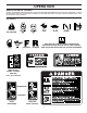
OPERATION KNOW YOUR SNOW THROWER READ THIS OWNER'S MANUAL AND ALL SAFETY RULES BEFORE OPERATING YOUR SNOW THROWER. Compare the illustrations with your snow thrower to familiarize yourself with the location of various controls and adjustments. Save this manual for future reference. These symbols may appear on your snow thrower or in literature supplied with the product. Learn and understand their meaning.
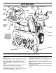
OPERATION SPARK PLUG SAFETY IGNITION KEY ENGINE OIL CAP WITH DIPSTICK AUGER CONTROL LEVER DISCHARGE CHUTE DRIVE CONTROL LEVER SPEED CONTROL LEVER GASOLINE FILLER CAP CHUTE DEFLECTOR CHOKE CONTROL TRACTION DRIVE CONTROL LEVER OIL DRAIN PLUG THROTTLE / ENGINE CONTROL DISCHARGE CHUTE RECOIL (AUXILIARY) STARTER HANDLE POWER CORD PLUG ELECTRIC START FUEL BUTTON SHUT-OFF VALVE PRIMER CLEANOUT TOOL HANDLE KNOB MUFFLER NOTE: ITEMS ABOVE ARE SHOWN IN THEIR TYPICAL LOCATION ON THE ENGINE.
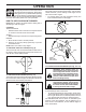
OPERATION The operation of any snow thrower can result in foreign objects thrown into the eyes, which can result in severe eye damage. Always wear safety glasses or eye shields while operating your snow thrower or performing any adjustments or repairs. We recommend standard safety glasses or a wide vision safety mask worn over spectacles. TO USE CHOKE CONTROL (See Fig. 11) The choke control is located on the engine. Use the choke control whenever you are starting a cold engine.
OPERATION • Press downward on chute deflector control lever and move lever forward to raise the deflector and increase the distance. Move lever back to lower the deflector and decrease the distance. Be sure lever springs back and locks into desired position. DISCHARGE CHUTE DISCHARGE CHUTE CONTROL LEVER CLEAN-OUT TOOL MOUNTING CLIP CHUTE DEFLECTOR REMOTE CONTROL LEVER FIG. 14 FIG. 13 • TO THROW SNOW (See Fig.
OPERATION TO ADJUST SKID PLATES (See Fig. 16) NOTE: The wrench provided in your parts bag may be used to adjust the skid plates. Skid plates are located on each side of the auger housing and adjust the clearance between the scraper bar and the ground surface. Adjust skid plates evenly to proper height for current surface conditions.
OPERATION BEFORE STOPPING Run the engine for a few minutes to help dry off any moisture on the engine. COLD START - ELECTRIC STARTER 1. Insert safety ignition key (packed separately in parts bag) into ignition slot until it clicks. DO NOT turn the key. Keep the extra safety ignition key in a safe place. 2. Place throttle control in “FAST” position. 3. Rotate choke control to “FULL” position. 4. Connect the power cord to the engine. 5.
MAINTENANCE GENERAL RECOMMENDATIONS The warranty on this snow thrower does not cover items that have been subjected to operator abuse or negligence. To receive full value from the warranty, operator must maintain snow thrower as instructed in this manual. Some adjustments will need to be made periodically to properly maintain your snow thrower. All adjustments in the Service and Adjustments section of this manual should be checked at least once each season.
MAINTENANCE 1. Remove safety ignition key and disconnect spark plug wire from spark plug. Place wire where it cannot come in contact with plug. 2. Clean area around drain plug. 3. Remove drain plug and drain oil in a suitable container. 4. Install drain plug and tighten securely. 5. Wipe off any spilled oil from snow thrower and engine. 6. Install left wheel (if removed for draining oil).
SERVICE AND ADJUSTMENTS WARNING: To avoid serious injury, before performing any service or adjustments: 1. Be sure throttle is in STOP position. 2. Remove safety ignition key. 3. Make sure the augers and all moving parts have completely stopped. 4. Remove safety ignition key and disconnect spark plug wire from spark plug. Place wire where it cannot contact plug. SNOW THROWER TO ADJUST SNOW THROWER HEIGHT See “TO ADJUST SKID PLATES” and “SCRAPER BAR” in the Operation section of this manual.
SERVICE AND ADJUSTMENTS 11. Place auger belt around and inside the groove of auger pulley only. 12. While your assistant slowly raises handles to rejoin the auger housing and frame assembly, pull up on the auger belt and squeeze sides together above pulley so belt is fully seated in groove of pulley. 13. Move idler arm so it does not hit impeller pulley as you bring snow thrower completely together and check carefully for proper routing of belts.
SERVICE AND ADJUSTMENTS TO REMOVE WHEELS (See Fig. 21) • Remove the klik pin and remove wheel from axle. IMPORTANT: When installing wheel, be sure to use the innermost hole in axle and the wheel hub hole. To disengage drive system from the wheels (for pushing or transporting the snow thrower), remove klik pin from wheel hub and insert pin into the outermost hole in axle only.
STORAGE OTHER CYLINDER 1. Remove spark plug. 2. Pour one ounce (29 ml) of oil through spark plug hole into cylinder. 3. Pull recoil starter handle slowly a few times to distribute oil. 4. Replace with new spark plug. • • • Remove safety ignition key; store it in a safe place. Do not store gasoline from one season to another. Replace your gasoline can if your can starts to rust. Rust and/or dirt in your gasoline will cause problems.
TROUBLESHOOTING See appropriate section in manual unless directed to a qualified service centre. PROBLEM Does not start CAUSE 1. Fuel shut-off valve (if so equipped) in OFF position. 2. Safety ignition key is not inserted. 3. Out of fuel. 4. Throttle in STOP position. 5. Choke in OFF position. 6. Primer not depressed. 7. Engine is flooded. 8. Spark plug wire is disconnected. 9. Bad spark plug. 10. Stale fuel. 11. Water in fuel. CORRECTION 1. Turn fuel shut-off valve to OPEN position. 2.
REPAIR PARTS SNOW THROWER - - MODEL NO. PR8527ES (96192001706) AUGER HOUSING / IMPELLER ASSEMBLY 1 3 (5x) 4 (5x) 2 01.07.002-A KEY NO. 1 2 3 4 PART NO. 404929X428 404932X479 72270505 155377 DESCRIPTION AUGER HOUSING 27 SCRAPER BAR CARRIAGE BOLT 5/16−18 X .625 NUT 5/16−18 2 3 1 1 2 3 01.07.024-B KEY NO. PART NO. DESCRIPTION 1 2 3 420478 411939 179582 AUGER BEARING BEARING PLUG SCREW 5/16−18 X 1.00 NOTE: All component dimensions given in U.S. inches. 1 inch = 25.
REPAIR PARTS SNOW THROWER - - MODEL NO. PR8527ES (96192001706) AUGER HOUSING / IMPELLER ASSEMBLY 2 1 01.07.018-A KEY NO. PART NO. DESCRIPTION 1 2 420495X479 420496X479 AUGER 27 LH AUGER 27 RH 3 4 2 4 3 01.11.001-A KEY NO. PART NO. DESCRIPTION 1 2 3 4 174762X479 178777X479 72270506 751153 SKID PLATE LH SKID PLATE RH CARRIAGE BOLT 5/16−18 X .75 NUT 5/16−18 1 NOTE: All component dimensions given in U.S. inches. 1 inch = 25.4 mm IMPORTANT: Use only Original Equipment Manufacturer (O.E.M.
REPAIR PARTS SNOW THROWER - - MODEL NO. PR8527ES (96192001706) AUGER HOUSING / IMPELLER ASSEMBLY 5 11 11 6 7 15 14 16 12 13 8 11 4 12 3 17 10 11 1 9 2 33 32 34 30 31 31 26 36 29 28 27 23 22 21 20 25 35 24 23 22 2 (EXPLODED) 21 18 19 01.07.004-B NOTE: All component dimensions given in U.S. inches. 1 inch = 25.4 mm IMPORTANT: Use only Original Equipment Manufacturer (O.E.M.) replacement parts. Failure to do so could be hazardous, damage your snow thrower and void your warranty.
REPAIR PARTS SNOW THROWER - - MODEL NO. PR8527ES (96192001706) AUGER HOUSING / IMPELLER ASSEMBLY KEY NO. PART NO.
REPAIR PARTS SNOW THROWER - - MODEL NO. PR8527ES (96192001706) CONTROL PANEL / DISCHARGE CHUTE 2 11 10 5 8 3 6 9 11 4 6 11 7 1 01.09.001-A KEY NO. PART NO. DESCRIPTION 1 2 3 4 5 6 7 8 9 10 11 404770X428 178633X428 420325 179096X479 189713X428 128415 185600 72270505 191730 155415 179246 CHUTE WELDMENT DEFLECTOR WELDMENT DEFLECTOR SEAL STRAP KNOB BLACK POP RIVET SHOULDER BOLT 1/4−20 X .704 CARRIAGE BOLT 5/16−18 X .625 NUT 1/4−20 WASHER PLASTIC WASHER NOTE: All component dimensions given in U.S.
REPAIR PARTS SNOW THROWER - - MODEL NO. PR8527ES (96192001706) CONTROL PANEL / DISCHARGE CHUTE 2 2 1 *3 *6 *6 KEY NO. PART NO. DESCRIPTION 1 2 *3 *4 *5 *6 420337 17501010 420678 420677 420675 420674 LEVER/CABLE ROTATOR ASSEMBLY SCREW 10−24 X .625 ROTATOR HEAD ROTATOR PIVOT BRACKET PULLEY PIVOT CABLE ASSEMBLY *4 01.09.007-A NOTES: 1. ITEMS INDICATED WITH AN * ARE LISTED AS REFERENCE FOR SERVICE PARTS ONLY. NOTE: All component dimensions given in U.S. inches. 1 inch = 25.
REPAIR PARTS HANDLES SNOW THROWER - - MODEL NO. PR8527ES (96192001706) 7 1 4 3 5 2 4 6 5 01.10.003-B 1 KEY NO. PART NO. DESCRIPTION 1 2 3 4 5 6 7 183346 178668 180927 184471 175262 178770 183784 CONSOLE PANEL HEADLIGHT BEZEL FLOOD HEADLIGHT SHOULDER SCREW 10−24 X .625 SCREW 10−24 X 1.25 WIRE HARNESS BULB KEY NO. 1 2 3 4 PART NO. 419797X479 418313X479 150078 17000616 DESCRIPTION LOWER TUBE PIVOT SUPPORT BOLT 5/16−18 X .750 SCREW 3/8−16 X 1.00 2 4 3 4 4 01.05.
SNOW THROWER - - MODEL NO. PR8527ES (96192001706) REPAIR PARTS HANDLES 3 4 3 4 4 1 3 4 3 2 01.08.004-B KEY NO. 1 2 3 4 PART NO. 419798X479 419799X479 74780524 751153 DESCRIPTION LOOP HANDLE LH LOOP HANDLE RH SCREW 5/16−18 X 1.50 NUT 5/16−18 NOTE: All component dimensions given in U.S. inches. 1 inch = 25.4 mm IMPORTANT: Use only Original Equipment Manufacturer (O.E.M.) replacement parts. Failure to do so could be hazardous, damage your snow thrower and void your warranty.
REPAIR PARTS HANDLES SNOW THROWER - - MODEL NO. PR8527ES (96192001706) 10 2 11 8 7 7 9 9 6 4 5 1 3 13 8 12 13 KEY NO. 1 2 3 4 5 6 7 8 9 10 11 12 13 14 PART NO. 412683X479 412681X479 412682X479 412679X008 420889X008 412677 421613 169675 17060408 414280 414281 178899 19131316 72120618 DESCRIPTION CONTROL PANEL CONTROL LEVER LH CONTROL LEVER RH TRACTION ROD ARM IMPELLER ROD ARM INTERLOCK ROD SPACER RETAINER SCREW 1/4−20 X .50 KNOB BLACK KNOB RED HANDLE KNOB WASHER 3/8 CARRIAGE BOLT 3/8−16 X 2.
SNOW THROWER - - MODEL NO. PR8527ES (96192001706) REPAIR PARTS HANDLES 2 10 10 3 1 8 KEY NO. 1 2 3 4 5 6 7 8 9 10 PART NO. 180480 405740 180445 187716 180447 178669 180926 72270506 155377 169675 DESCRIPTION IMPELLER ROD ASSEMBLY TRACTION ROD ASSEMBLY SHIFTER ROD TOP SHIFTER ROD BOTTOM SPRING SLEEVE IMPELLER SPRING TRACTION SPRING CARRIAGE BOLT 5/16−18 X .75 NUT 5/16−18 RETAINER 9 4 5 10 7 5 01.12.001-B 6 NOTE: All component dimensions given in U.S. inches. 1 inch = 25.
SNOW THROWER - - MODEL NO. PR8527ES (96192001706) REPAIR PARTS DRIVE ITEM 43 EXPLODED 2 69 68 16 1 71 17 18 15 11 9 9 8 10 12 9 14 70 15 20 11 76 13 72 22 11 4 34 7 76 73 24 19 76 23 75 21 6 24 5 33 23 76 3 28 26 29 30 31 33 32 35 35 50 39 36 76 27 24 26 47 37 4 38 24 76 25 43 44 40 42 41 49 51 52 53 45 46 23 74 49 48 54 55 56 67 62 61 63 64 59 4 40 01.02.003-D 49 51 57 58 60 66 NOTE: All component dimensions given in U.S. inches.
REPAIR PARTS DRIVE KEY NO. 1 2 3 4 5 6 7 8 9 10 11 12 13 14 15 16 17 18 19 20 21 22 23 24 25 26 27 28 29 30 31 32 33 34 35 36 37 38 PART NO. 198474 17501010 402685X428 17490508 57079 405485 198580 403097X004 402881 403096X004 191730 402856X004 416717X004 187101 700279 406109 402568 169675 401732 402310 402882 402878 751153 408981 73930500 198176X479 179831 175344 178613 74760514 12000012 402187 401619 417234 17490408 401984X479 180135 402652 SNOW THROWER - - MODEL NO.
SNOW THROWER - - MODEL NO. PR8527ES (96192001706) REPAIR PARTS DRIVE 5 6 1b 7 4 3 1b 1a 6 2 3 5 4 01.03.005-B KEY NO. 1 1a 1b 2 3 4 5 6 7 PART NO. 188226 179352 9465M1 402691 174697 179830 17490508 155443 189282 DESCRIPTION (assy of 1a,1b) AXLE ASSEMBLY AXLE SHAFT ROLL PIN 3/16 SPROCKET THRUST WASHER BEARING BOLT 5/16−18 X .500 CLIK PIN SQUARE KEY NOTE: All component dimensions given in U.S. inches. 1 inch = 25.4 mm IMPORTANT: Use only Original Equipment Manufacturer (O.E.M.) replacement parts.
REPAIR PARTS SNOW THROWER - - MODEL NO. PR8527ES (96192001706) CHASSIS / ENGINE / PULLEYS 4 2 3 4 3 1 01.00.008-B KEY NO. PART NO. - ------ 1 2 3 4 409346X428 423184X428 150406 150078 DESCRIPTION ENGINE, TEC MODEL LH318SA-156551H FRAME ENGINE MOUNT PLATE BOLT 3/8−16 SCREW 5/16−18 X .750 NOTE: All component dimensions given in U.S. inches. 1 inch = 25.4 mm IMPORTANT: Use only Original Equipment Manufacturer (O.E.M.) replacement parts.
REPAIR PARTS SNOW THROWER - - MODEL NO. PR8527ES (96192001706) CHASSIS / ENGINE / PULLEYS 1 KEY NO. PART NO. DESCRIPTION 1 2 3 4 192213 179157 419744 408007 BELT COVER IMPELLER PULLEY TRACTION BELT IMPELLER BELT 2 3 4 01.04.019-A NOTE: All component dimensions given in U.S. inches. 1 inch = 25.4 mm IMPORTANT: Use only Original Equipment Manufacturer (O.E.M.) replacement parts. Failure to do so could be hazardous, damage your snow thrower and void your warranty.
REPAIR PARTS WHEELS SNOW THROWER - - MODEL NO. PR8527ES (96192001706) 1 2 KEY NO. PART NO. DESCRIPTION 1 2 187833X421 187865X421 WHEEL ASSEMBLY LH WHEEL ASSEMBLY RH 01.06.002-A NOTE: All component dimensions given in U.S. inches. 1 inch = 25.4 mm IMPORTANT: Use only Original Equipment Manufacturer (O.E.M.) replacement parts. Failure to do so could be hazardous, damage your snow thrower and void your warranty.
SNOW THROWER - - MODEL NO. PR8527ES (96192001706) REPAIR PARTS BAG OF PARTS 3 5 4 KEY NO. PART NO. DESCRIPTION 1 2 3 4 5 6 7 8 198563 169675 180684 73800600 19131316 198636 198638 73800400 POWER CORD RETAINER PIN WRENCH LOCKNUT 3/8−16 WASHER 3/8 SHEAR BOLT 1/4−20 X 1−3/4 SPACER LOCKNUT 1/4−20 2 8 1 7 6 01.14.004-A 1 KEY NO. PART NO. DESCRIPTION 1 35062 SAFETY IGNITION KEY 01.14.008-A NOTE: All component dimensions given in U.S. inches. 1 inch = 25.
REPAIR PARTS DECALS 1 SNOW THROWER - - MODEL NO. PR8527ES (96192001706) 2 4 9 8 6 5 1 3 KEY NO. PART NO. DESCRIPTION 1 2 3 4 5 6 7 8 9 --- 181037 187871 181035 181042 187870 181033 415391 415390 415475 421899 421900 DECAL, DANGER DECAL, POULON PRO, 8.5 HP/27" DECAL, DANGER, DEFLECTOR DECAL, DANGER DECAL, POULON PRO DECAL, INSTRUCTION DECAL, TRACTION LEVER DECAL, AUGER LEVER DECAL, SPEED CONTROL OWNER’S MANUAL, ENGLISH OWNER'S MANUAL, FRENCH NOTE: All component dimensions given in U.S. inches.
SERVICE NOTES 38
SERVICE NOTES 39
LIMITED WARRANTY The Manufacturer warrants to the original consumer purchaser that this product as manufactured is free from defects in materials and workmanship. For a period of two (2) years from date of purchase by the original consumer purchaser, we will repair or replace, at our option, without charge for parts or labor incurred in replacing parts, any part which we find to be defective due to materials or workmanship. This Warranty is subject to the following limitations and exclusions. 1.