IMPORTANT MANUAL Do Not Throw Away OWNER'S MANUAL MODEL NUMBER: 961980022 SNOW THROWER WARNING: Read the Owner's Manual and follow all Warnings and Safety Instructions. Failure to do so can result in serious injury. Always Wear Eye Protection During Operation 420925 08.11.08 SBW/TH Printed in U.S.A.
IMPORTANT Safe Operation Practices for Walk-Behind Snow Throwers This snow thrower is capable of amputating hands and feet and throwing objects. Failure to observe the following safety instructions could result in serious injury. WARNING: Snow throwers have exposed rotating parts, which can cause severe injury from contact, or from material thrown from the discharge chute. Keep the area of operation clear of all persons, small children and pets at all times including startup.
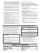
6. When cleaning, repairing or inspecting the snow thrower, stop the engine and make certain the collector/impeller and all moving parts have stopped. Disconnect the spark plug wire and keep the wire away from the plug to prevent someone from accidentally starting the engine. 7. Do not run the engine indoors, except when starting the engine and for transporting the snow thrower in or out of the building. Open the outside doors; exhaust fumes are dangerous. 8.
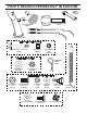
PARTS PACKED SEPARATELY IN CARTON (1) MULTIWRENCH (180684) (1) SAFTEY IGNITION KEY (35062) (1) POWER CORD (198563) (1) AUGER CONTROL ROD (1) TRACTION DRIVE CONTROL ROD (1) DISCHARGE CHUTE EXTRA SHEAR BOLTS AND NUTS (2) SHEAR BOLTS 1/4-20 x 1-3/4 (198636) (2) LOCKNUTS 1/4-20 (73800400) (2) SPACERS (198638) ROTATOR HEAD MOUNTING (3) RETAINER SPRINGS (169675) (1) WASHER 3/8 (19131316) (1) LOCKNUT 3/8 (73800600) CHUTE DEFLECTOR REMOTE CONTROL (1) LOCKNUT 5/16-18 (751153) (1) CARRIAGE BOLT 5/16-18 x
ASSEMBLY / PRE-OPERATION Read these instructions and this manual in its entirety before you attempt to assemble or operate your new snow thrower. Reading the entire manual will familiarize you with the unit, which will assist you in assembly, operation and maintenance of the product. Your new snow thrower has been assembled at the factory with the exception of those parts left unassembled for shipping purposes. All parts such as nuts, washers, bolts, etc.
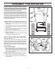
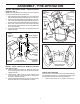
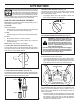
ASSEMBLY / PRE-OPERATION INSTALL TRACTION DRIVE CONTROL ROD (See Figs. 3 and 4) The traction drive control rod has the long loop on the end of the spring as shown. 1. Slide rubber sleeve up rod and hook end of spring into pivot bracket with loop opening down as shown. 2. With top end of rod positioned under left side of control panel, push rod down and insert top end of rod into hole in drive control bracket. Secure with retainer spring. INSTALL AUGER CONTROL ROD (See Figs.
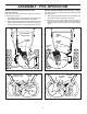
ASSEMBLY / PRE-OPERATION INSTALL DISCHARGE CHUTE / CHUTE ROTATOR HEAD (See Fig. 7) NOTE: The multi-wrench provided in your parts bag may be used to install the chute rotator head. 1. Place discharge chute assembly on top of chute base with discharge opening toward front of snow thrower. 2. Position chute rotator head over chute bracket. If necessary, rotate chute assembly to align square and pin on underside of chute rotator head with holes in chute bracket. 3.
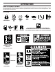
OPERATION KNOW YOUR SNOW THROWER READ THIS OWNER'S MANUAL AND ALL SAFETY RULES BEFORE OPERATING YOUR SNOW THROWER. Compare the illustrations with your snow thrower to familiarize yourself with the location of various controls and adjustments. Save this manual for future reference. These symbols may appear on your snow thrower or in literature supplied with the product. Learn and understand their meaning.
OPERATION SPARK PLUG SAFETY IGNITION KEY AUGER CONTROL LEVER ENGINE OIL CAP WITH DIPSTICK GASOLINE FILLER CAP DISCHARGE CHUTE CONTROL LEVER DRIVE SPEED CONTROL LEVER CHUTE DEFLECTOR CHOKE CONTROL OIL DRAIN PLUG THROTTLE / ENGINE CONTROL RECOIL (AUXILIARY) STARTER HANDLE POWER CORD ELECTRIC PLUG START BUTTON LH TURN TRIGGER DISCHARGE CHUTE LIGHT FUEL SHUT-OFF VALVE PRIMER DEFLECTOR REMOTE CONTROL LEVER TRACTION DRIVE CONTROL LEVER CLEANOUT TOOL HANDLE KNOB MUFFLER NOTE: ITEMS ABOVE ARE SHOWN
OPERATION The operation of any snow thrower can result in foreign objects thrown into the eyes, which can result in severe eye damage. Always wear safety glasses or eye shields while operating your snow thrower or performing any adjustments or repairs. We recommend standard safety glasses or a wide vision safety mask worn over spectacles. 00155 TO USE CHOKE CONTROL (See Fig. 13) The choke control is located on the engine. Use the choke control whenever you are starting a cold engine.
OPERATION TO THROW SNOW (See Fig. 15) The auger rotation is controlled by the auger control lever located on the right side handle. • Squeeze auger control lever to handle to engage the auger and throw snow. • Release the auger control lever to stop throwing snow. AUGER CONTROL LEVER • Squeeze traction drive control lever to handle to engage the drive system. • Release traction drive control lever to stop the forward or reverse movement of the snow thrower.
OPERATION BEFORE STARTING THE ENGINE ground surface. Adjust skid plates evenly to proper height for current surface conditions. For removal of snow in normal conditions, such as a paved driveway or sidewalk, place skid plates in the highest position (lowest scraper clearance) to give a 1/8" clearance between the scraper bar and the ground. Use a middle position if the surface to be cleared is uneven. NOTE: It is not recommended to operate the snow thrower over gravel or rocky surfaces.
OPERATION 6. When the engine starts, release the recoil starter handle and slowly move the choke control to the “OFF” position. Allow the engine to warm up for a few minutes. Engine will not develop full power until it has reached normal operating temperature. WARM START - RECOIL STARTER Follow the steps above, keeping the choke in the “OFF” position. DO NOT push the primer. TO START ENGINE • Be sure fuel shut-off valve is in the “OPEN” position. Your snow thrower engine is equipped with both a 120 Volt A.
MAINTENANCE GENERAL RECOMMENDATIONS The warranty on this snow thrower does not cover items that have been subjected to operator abuse or negligence. To receive full value from the warranty, operator must maintain snow thrower as instructed in this manual. Some adjustments will need to be made periodically to properly maintain your snow thrower. All adjustments in the Service and Adjustments section of this manual should be checked at least once each season.
MAINTENANCE AUGER GEAR CASE • The gear case was filled with lubricant to the proper level at the factory. The only time the lubricant needs attention is if service has been performed on the gear case. • If lubricant is required, use only Ronex ED #1 grease. • Oil will drain more freely when warm. • Catch oil in a suitable container. NOTE: The left side wheel may be removed from snow thrower for easier access to the oil drain plug and placement of a suitable container.
SERVICE AND ADJUSTMENTS WARNING: To avoid serious injury, before performing any service or adjustments: 1. Be sure throttle is in STOP position. 2. Remove safety ignition key. 3. Make sure the augers and all moving parts have completely stopped. 4. Disconnect spark plug wire from spark plug and place wire where it cannot contact plug. SNOW THROWER 3. Align holes in impeller hub with holes in impeller shaft and install two (2) new 1/4-20 x 1-5/8" capscrew/shear bolts.
SERVICE AND ADJUSTMENTS be replaced. It is recommended that the belt(s) be replaced by a qualified service center. NOTE: It is recommended that both the auger and traction drive belt be replaced at the same time. The V-belts on your snow thrower are of special construction and should be replaced by original equipment manufacturer (OEM) belts available from your nearest dealer. Using other than OEM belts can cause personal injury or damage to the snow thrower.
SERVICE AND ADJUSTMENTS KLIK PIN (INSTALL IN OUTER HOLE OF AXLE ONLY) CARBURETOR Your carburetor is not adjustable. Engine performance should not be affected at altitudes up to 7,000 feet (2,134 meters). If your engine does not operate properly due to suspected carburetor problems, take your snow thrower to a qualified service center. OUTER HOLE ENGINE SPEED Never tamper with the engine governor, which is factory set for proper engine speed.
TROUBLESHOOTING See appropriate section in manual unless directed to a qualified service centre. PROBLEM Does not start CAUSE 1. Fuel shut-off valve (if so equipped) in OFF position. 2. Safety ignition key is not inserted. 3. Out of fuel. 4. Throttle in STOP position. 5. Choke in OFF position. 6. Primer not depressed. 7. Engine is flooded. 8. Spark plug wire is disconnected. 9. Bad spark plug. 10. Stale fuel. 11. Water in fuel. CORRECTION 1. Turn fuel shut-off valve to OPEN position. 2.
REPAIR PARTS SNOW THROWER - MODEL 961980022 (96198002200) AUGER HOUSING / IMPELLER ASSEMBLY 5 11 11 6 7 15 14 16 12 13 8 11 4 12 3 17 10 11 1 9 2 33 32 34 30 31 31 26 36 29 28 27 23 22 21 20 25 35 24 23 22 2 (EXPLODED) 21 18 19 01.07.004-B NOTE: All component dimensions given in U.S. inches. 1 inch = 25.4 mm IMPORTANT: Use only Original Equipment Manufacturer (O.E.M.) replacement parts. Failure to do so could be hazardous, damage your snow thrower and void your warranty.
REPAIR PARTS SNOW THROWER - MODEL 961980022 (96198002200) AUGER HOUSING / IMPELLER ASSEMBLY KEY NO. PART NO.
REPAIR PARTS SNOW THROWER - MODEL 961980022 (96198002200) AUGER HOUSING / IMPELLER ASSEMBLY 1 3 (5x) 4 (5x) 2 01.07.003-A KEY NO. PART NO. DESCRIPTION 1 2 3 4 404930X428 404933X479 72270505 155377 AUGER HOUSING SCRAPPER BAR CARRIAGE BOLT 5/16−18 X .625 NUT 5/16−18 2 3 1 1 2 KEY NO. PART NO. DESCRIPTION 1 2 3 420478 411939 179582 AUGER BEARING BEARING PLUG SCREW 5/16−18 X 1.00 3 01.07.024-B NOTE: All component dimensions given in U.S. inches. 1 inch = 25.
REPAIR PARTS SNOW THROWER - MODEL 961980022 (96198002200) AUGER HOUSING / IMPELLER ASSEMBLY 2 1 KEY NO. PART NO. DESCRIPTION 1 2 420497X479 420498X479 AUGER ASSEMBLY 30 LH AUGER ASSEMBLY 30 RH 01.07.019-A 3 4 2 4 3 01.11.001-A KEY NO. PART NO. DESCRIPTION 1 2 3 4 174762X479 178777X479 72270506 751153 SKID PLATE LH SKID PLATE RH CARRIAGE BOLT 5/16−18 X .75 NUT 5/16−18 1 NOTE: All component dimensions given in U.S. inches. 1 inch = 25.
REPAIR PARTS SNOW THROWER - MODEL 961980022 (96198002200) AUGER HOUSING / IMPELLER ASSEMBLY 1 4 5 1 3 4 4 3 5 3 2 2 3 4 01.16.001-A KEY NO. PART NO. DESCRIPTION 1 2 3 4 5 181160X479 72270506 179246 10040500 128638 DRIFT CUTTER BAR CARRIAGE BOLT 5/16−18 X .750 PLASTIC WASHER LOCKWASHER 5/16 NUT 5/16−18 KEY NO. PART NO. DESCRIPTION 1 2 3 182516 72110510 751153 WEIGHT BAR CARRIAGE BOLT 5/16−18 X 1.25 NUT 5/16−18 2 1 2 3 01.17.003-A 3 NOTE: All component dimensions given in U.S.
REPAIR PARTS SNOW THROWER - MODEL 961980022 (96198002200) CONTROL PANEL / DISCHARGE CHUTE 2 2 1 *3 *6 *6 KEY NO. PART NO. DESCRIPTION 1 2 *3 *4 *5 *6 420337 17501010 420678 420677 420675 420674 LEVER/CABLE ROTATOR ASSEMBLY SCREW 10−24 X .625 ROTATOR HEAD ROTATOR PIVOT BRACKET PULLEY PIVOT CABLE ASSEMBLY *4 01.09.007-A *5 NOTES: 1. ITEMS INDICATED WITH AN * ARE LISTED AS REFERENCE FOR SERVICE PARTS ONLY. 2 1 KEY NO. PART NO. DESCRIPTION 1 2 188303 74041024 STEER CABLE SCREW 10−24 X 1.
REPAIR PARTS SNOW THROWER - MODEL 961980022 (96198002200) CONTROL PANEL / DISCHARGE CHUTE 5 7 3 14 15 *13 *10 *9 2 4 KEY NO. PART NO. DESCRIPTION 1 2 3 4 5 6 7 *8 *9 *10 *11 *12 *13 14 15 404770X428 178633X428 420673 420325 414280 128415 17501010 179829 179246 191730 72250505 751153 184505 420679 420672 CHUTE WELDMENT 6 DEFLECTOR WELDMENT DEFLECTOR CONTROL ASSEMBLY DEFLECTOR SEAL KNOB BLACK 1 POP RIVET SCREW 10−24 X .625 SHOULDER SCREW PLASTIC WASHER NUT 1/4−20 CARRIAGE BOLT 5/16−18 X .
SNOW THROWER - MODEL 961980022 (96198002200) REPAIR PARTS HANDLES 10 1 5 6 10 8 7 2 5 3 8 6 KEY NO. PART NO. DESCRIPTION 1 2 3 4 5 6 7 8 9 10 419800X479 419801X479 196944 196943 414515 74780512 74780524 751153 155415 178775 PLOW HANDLE LH PLOW HANDLE RH PANEL BRACKET LH PANEL BRACKET RH HEATED HANDLE GRIP CREW 5/16−18 X .750 SCREW 5/16−18 X 1.50 NUT 5/16−18 WASHER POP RIVET 1/8 9 7 8 4 9 01.08.005-A 4 3 2 5 1 6 01.08.007-B KEY NO. PART NO.
REPAIR PARTS HANDLES SNOW THROWER - MODEL 961980022 (96198002200) 10 2 11 8 4 7 9 9 5 6 7 1 3 13 8 KEY NO. PART NO. DESCRIPTION 1 2 3 4 5 6 7 8 9 10 11 12 13 14 412683X479 412681X479 412682X479 412679X008 420889X008 412677 412680 169675 17060408 414280 414281 178899 19131316 72120618 CONTROL PANEL CONTROL LEVER LH CONTROL LEVER RH TRACTION ROD ARM IMPELLER ROD ARM INTERLOCK ROD SPACER RETAINER SCREW 1/4−20 X .50 KNOB BLACK KNOB RED HANDLE KNOB WASHER 3/8 CARRIAGE BOLT 3/8−16 X 2.
REPAIR PARTS HANDLES SNOW THROWER - MODEL 961980022 (96198002200) 2 1 3 8 KEY NO. PART NO. DESCRIPTION 1 2 3 4 5 6 7 8 9 10 180480 405740 180445 187716 180447 178669 180926 72270506 155377 169675 IMPELLER ROD ASSEMBLY TRACTION ROD ASSEMBLY SHIFTER ROD TOP SHIFTER ROD BOTTOM SPRING SLEEVE IMPELLER SPRING TRACTION SPRING CARRIAGE BOLT 5/16−18 X .75 NUT 5/16−18 RETAINER 9 4 5 7 10 5 6 01.12.001-A NOTE: All component dimensions given in U.S. inches. 1 inch = 25.
REPAIR PARTS HANDLES SNOW THROWER - MODEL 961980022 (96198002200) KEY NO. PART NO. DESCRIPTION 1 2 3 4 5 6 7 8 413927 178668 178666 184471 175262 417760 405699 401620 CONSOLE PANEL BLACK 3 HEADLIGHT BEZEL HALOGEN HEADLIGHT SHOULDER SCREW 10−24 X .625 SCREW 10−24 X 1.25 GRIP SWITCH WIRE HARNESS BULB 6 1 4 8 5 2 4 5 7 01.10.004-B 1 KEY NO. PART NO. DESCRIPTION 1 2 3 4 419797X479 405784X479 150078 17000616 LOWER HANDLE PIVOT SUPPORT WELDMENT SCREW 5/16−18 X .750 SCREW 3/8−16 X 1.
SNOW THROWER - MODEL 961980022 (96198002200) REPAIR PARTS DRIVE 6 7 1b 8 1a 2 3 4 6 3 1b 7 5 4 01.03.002-A KEY NO. PART NO. DESCRIPTION 1 1a 1b 2 3 4 5 6 7 8 404923 404307 9465M1 402691 174697 179830 146315 17490508 155443 189282 AXLE ASSEMBLY (assy of 1a,1b) AXLE SHAFT ROLL PIN 3/16 X 1.50 SPROCKET THRUST WASHER BEARING SCREW 5/16−18 X .625 SCREW 5/16−18 X .500 KLIK PIN 1/4 X 1.50 SQUARE KEY NOTE: All component dimensions given in U.S. inches. 1 inch = 25.
SNOW THROWER - MODEL 961980022 (96198002200) REPAIR PARTS DRIVE ITEM 43 EXPLODED 2 68 16 1 69 71 17 18 15 14 9 9 10 8 7 6 11 12 9 70 15 20 11 4 13 72 22 11 4 34 4 73 24 19 4 23 75 21 24 5 33 23 4 3 28 26 29 30 31 33 32 35 35 50 39 36 4 27 24 26 47 37 4 38 24 4 25 43 44 40 49 51 52 53 45 46 23 74 49 48 54 55 56 49 51 57 58 67 62 61 42 41 40 64 63 59 4 01.02.006-D 60 66 NOTE: All component dimensions given in U.S. inches. 1 inch = 25.
REPAIR PARTS DRIVE SNOW THROWER - MODEL 961980022 (96198002200) KEY NO. PART NO.
REPAIR PARTS SNOW THROWER - MODEL 961980022 (96198002200) CHASSIS / ENGINE / PULLEYS 4 2 3 4 3 1 01.00.008-A KEY NO. PART NO. - ------ 1 2 3 4 409346X428 417014X428 150406 150078 ENGINE, TEC, MODEL OH318SA-221835B FRAME ENGINE MOUNT PLATE BOLT 3/8−16 SCREW 5/16−18 X .750 KEY NO. PART NO. DESCRIPTION 1 35062 SAFETY IGNITION KEY DESCRIPTION 1 01.14.008-A NOTE: All component dimensions given in U.S. inches. 1 inch = 25.4 mm IMPORTANT: Use only Original Equipment Manufacturer (O.E.M.
REPAIR PARTS SNOW THROWER - MODEL 961980022 (96198002200) CHASSIS / ENGINE / PULLEYS 1 2 KEY NO. PART NO. DESCRIPTION 1 2 3 4 192213 179157 419744 408007 BELT COVER IMPELLER PULLEY TRACTION BELT IMPELLER BELT 3 4 01.04.019-A NOTE: All component dimensions given in U.S. inches. 1 inch = 25.4 mm IMPORTANT: Use only Original Equipment Manufacturer (O.E.M.) replacement parts. Failure to do so could be hazardous, damage your snow thrower and void your warranty.
REPAIR PARTS WHEELS SNOW THROWER - MODEL 961980022 (96198002200) 1 2 01.06.006-A KEY NO. PART NO. DESCRIPTION 1 2 196752X421 196753X421 WHEEL ASSEMBLY LH WHEEL ASSEMBLY RH 3 1 2 01.15.003-A KEY NO. PART NO. DESCRIPTION 1 2 3 410293 410294 17060410 CABLE BRACKET LH CABLE BRACKET RH SCREW 1/4−20 X .625 NOTE: All component dimensions given in U.S. inches. 1 inch = 25.4 mm IMPORTANT: Use only Original Equipment Manufacturer (O.E.M.) replacement parts.
SNOW THROWER - MODEL 961980022 (96198002200) REPAIR PARTS WHEELS 2 17 20 16 18 15 18 24 17 16 20 19 2 3 2 1 4 5 6 23 22 7 8 9 7 22 11 21 21 11 10 4 23 19 14 12 13 13 14 10 9 6 3 5 8 12 01.15.001-A KEY NO. PART NO. DESCRIPTION KEY NO. PART NO.
REPAIR PARTS BAG OF PARTS SNOW THROWER - MODEL 961980022 (96198002200) 4 6 5 7 9 8 3 10 2 1 11 14 13 12 01.14.003-A KEY NO. PART NO.
REPAIR PARTS DECALS SNOW THROWER - MODEL 961980022 (96198002200) 9 8 1 6 2 4 1 3 5 10 7 KEY NO. PART NO.
LIMITED WARRANTY The Manufacturer warrants to the original consumer purchaser that this product as manufactured is free from defects in materials and workmanship. For a period of two (2) years from date of purchase by the original consumer purchaser, we will repair or replace, at our option, without charge for parts or labor incurred in replacing parts, any part which we find to be defective due to materials or workmanship. This Warranty is subject to the following limitations and exclusions. 1.